Passive vs. Active Components in LTCC Ceramic Substrates: Key Differences and Applications
Low-Temperature Co-Fired Ceramic (LTCC) technology has revolutionized modern electronics by enabling compact, high-frequency, and reliable circuit integration. A critical aspect of LTCC design lies in understanding how passive components (resistors, capacitors, inductors)and active components (transistors, ICs, sensors) are implemented within these multilayer ceramic substrates. While both play vital roles, their integration methods, performance characteristics, and applications differ dramatically. This blog explores these differences and their implications for advanced electronic systems.
What is LTCC Technology?
LTCC involves stacking unfired ("green") ceramic layers printed with conductive traces and passive components, followed by co-firing at 850–900°C. The result is a dense, 3D substrate with embedded circuitry, ideal for RF, automotive, and aerospace applications. Key advantages include:
- High-frequency stability (up to 100+ GHz)
- Excellent thermal/mechanical robustness
- Multilayer integration (10–30+ layers)
- Miniaturization through embedded passives
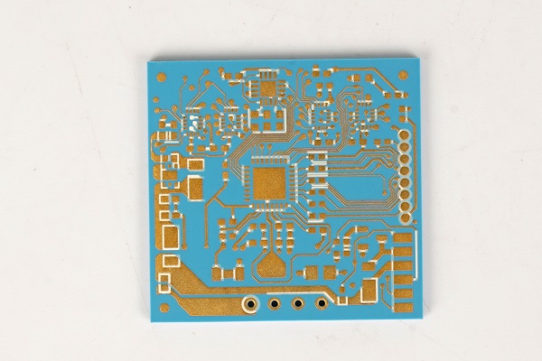
Passive Components in LTCC: The Backbone of Integration
1. Seamless Multilayer Embedding
Passive components are directly fabricated within LTCC layers during manufacturing:
- Capacitors: Created by sandwiching dielectric paste between conductive layers.
- Example: A 10-layer LTCC module can embed 50+ capacitors for decoupling and filtering.
- Inductors: Formed via spiral or meander-shaped traces.
- Design Tip: Air-core inductors avoid magnetic losses, achieving Q-factors >50 at 2.4 GHz.
- Resistors: Screen-printed using resistive pastes (e.g., RuO₂, LaB₆).
- Tolerance: ±20% (standard) vs. ±5% (laser-trimmed).
Advantages:
- 60–80% size reduction vs. surface-mount passives.
- Eliminates solder joints, improving reliability in harsh environments.
2. High-Frequency Dominance
LTCC’s low dielectric loss (tan δ < 0.002) makes it ideal for RF/microwave passives:
- Filters: Bandpass/bandstop filters for 5G base stations.
- Baluns: Integrated in Bluetooth/Wi-Fi modules for impedance matching.
- Antennas: Miniaturized patch antennas in IoT sensors.
Case Study: A 28 GHz 5G phased-array antenna uses LTCC-embedded inductors to reduce feedline losses by 40%.
3. 3D Electromagnetic Optimization
LTCC allows vertical stacking of:
- Signal layers
- Ground/power planes
- Shielded cavities
This enables:
- Reduced crosstalk in mixed-signal designs.
- Controlled impedance for high-speed digital lines.
Active Components in LTCC: Challenges and Hybrid Solutions
1. Surface-Mount Dominance
Most active devices (ICs, amplifiers) cannot be embedded due to LTCC’s thermal limits. Instead, they’re mounted post-firing:
- SMT (Surface-Mount Technology): Soldered onto pads/pins.
- Example: A GPS module combines LTCC-embedded passives with a surface-mounted RFIC.
- Wire Bonding/Flip-Chip: For high-I/O devices like FPGAs.
Limitations:
- Increased footprint vs. embedded passives.
- Solder joints may fail under thermal cycling.
2. Process Compatibility Hurdles
Active components require semiconductor fabrication (e.g., Si, GaAs), which clashes with LTCC’s processing:
- Temperature Mismatch: LTCC sinters at 850°C, while ICs degrade above 450°C.
- Material Incompatibility: Semiconductor dopants may contaminate LTCC layers.
Exception: Some MEMS sensors (e.g., pressure sensors) can be integrated via sacrificial layer techniques.
3. System-in-Package (SiP) Innovations
LTCC acts as a substrate for heterogenous integration:
- Embedded Dies: Bare ICs placed in cavities, connected via microvias.
- Chip-on-Ceramic: Thinned dies bonded to LTCC (common in automotive radars).
- 3D Fan-Out: Redistribute chip I/Os across LTCC layers.
Real-World Application: Automotive radar modules use LTCC SiP to combine MMIC amplifiers, embedded antennas, and thermal vias.
Key Differences at a Glance
|
Aspect |
Passive Components |
Active Components |
|
Integration |
Embedded during lamination |
Surface-mounted post-firing |
|
Process Temp |
Compatible with 850°C sintering |
Require low-temp assembly (<300°C) |
|
Function |
Signal conditioning, filtering |
Signal processing, control logic |
|
Size Impact |
Reduce footprint by 3D embedding |
Increase module size |
|
Reliability |
Immune to solder fatigue |
Dependent on interconnect integrity |
Applications
1. 5G RF Front-End Modules
- Passives: LTCC-embedded duplexers, matching networks.
- Actives: GaN PA chips soldered externally.
- Outcome: 30% smaller vs. PCB-based designs.
2. Automotive Engine Control Units (ECUs)
- Passives: Buried resistors for sensor signal conditioning.
- Actives: MCU and CAN transceivers mounted on top.
- Benefit: Operates reliably at 150°C underhood temperatures.
3. Satellite Communication Systems
- Passives: Radiation-hardened filters and couplers.
- Actives: Rad-tolerant FPGAs in hermetic packages.
Future Trends
1. Co-Fired Active Layers
Research into low-temperature semiconductor pastes (e.g., printable Si inks) could enable fully embedded actives.
2. Photonic Integration
LTCC waveguides + embedded laser diodes for optoelectronic systems.
3. AI-Driven Design
Machine learning optimizes 3D layouts for minimal EMI and maximum density.
Conclusion
While passive components leverage LTCC’s 3D integration capabilities to achieve unprecedented miniaturization, active devices remain reliant on hybrid assembly techniques. This dichotomy defines LTCC’s role as a "passive-enabling, active-supporting" platform. As materials science and packaging technologies advance, the line between passives and actives in LTCC may blur—ushering in a new era of monolithic ceramic-based systems.
For engineers, mastering this balance is key to unlocking LTCC’s full potential in next-gen electronics.



























 HOME
HOME


