






















































 HOME
HOME


-

Ceramic PCB for Humanoid Robot joint actuators
2026 04,07 -
LTCC PCB Surprises: What Most People Miss
2025 12,09 -
Step-by-Step Guide to DPC PCB Design for Sensor Systems
2025 12,03 -
Ceramic PCBs Essential Benefits and Applications
2025 12,01 -
How Al2O3 DPC Ceramic Substrate PCB Enhances Heat Dissipation in Modern Electronics?
2025 11,28 -
How to Choose Between Ceramic, FR4, and Metal Core PCBs
2025 11,27 -
DPC Ceramic PCB Materials: Surprising Science Inside
2025 11,26 -
Wire bondable 2-layer Alumina substrates PCB | Bstceramic PCB
2025 09,22 -
Silicon Nitride Substrate, Silicon Nitride Ceramic Substrate Formula
2025 05,08 -
What is thick film ceramic PCB?
2023 08,02
Ceramic Circuit Board Material Selection: Alumina, AlN, Si3N4 and Process Matching
Published:
Ceramic circuit board material determines far more than the nominal thermal conductivity of a board. Alumina, aluminum nitride and silicon nitride have different heat-transfer capability, thermal expansion, dielectric behavior, fracture resistance and compatible copper processes. A useful selection therefore connects the ceramic grade to substrate thickness, copper geometry, metallization method, assembly stress and the operating environment.
What Is Ceramic Circuit Board Material?
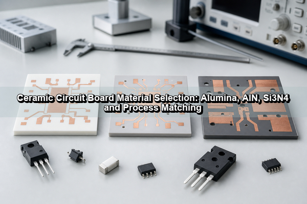
Ceramic circuit board material is an inorganic electrical insulator used as the structural and thermal base of a printed circuit. Unlike FR4, which combines glass fabric with epoxy resin, a ceramic printed circuit board uses a fired oxide or nitride substrate beneath its conductors. The ceramic supports traces and components while also carrying heat through the board thickness.
The substrate and the conductor system must be treated as one construction. A ceramic tile without metallization is not yet a PCB, and identical ceramic grades can behave differently when paired with thin plated copper, thick bonded copper or printed conductors. This is why the terms ceramic PCB material, ceramic substrate and ceramic circuit board describe related but not interchangeable parts of the design.
Which Materials Are Used in Ceramic Circuit Boards?
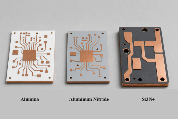
Alumina, aluminum nitride and silicon nitride are the three materials most often compared for modern electronic substrates. Beryllium oxide also transfers heat efficiently, but dust created during machining or damage presents a serious health hazard. Many new designs use AlN instead when high thermal conductivity is required without the same material-handling concern.
- Alumina (Al2O3): mature, electrically insulating and available in several purity grades. It is the practical baseline for many ceramic circuits.
- Aluminum nitride (AlN): selected when the ceramic layer must move substantially more heat and its expansion should remain closer to silicon.
- Silicon nitride (Si3N4): selected when fracture toughness, vibration resistance and repeated thermal cycling are more important than maximum conductivity.
- LTCC and HTCC: co-fired ceramic systems used for multilayer interconnects and embedded conductors. They are manufacturing platforms rather than direct substitutes for every single-layer Alumina, AlN or Si3N4 board.
How Do Alumina, AlN, and Si3N4 Compare?
The quickest comparison is to identify which constraint dominates: cost, heat flow or thermomechanical reliability. Values vary by composition and supplier, so a qualified material datasheet must govern the final design.
| Property | Alumina | AlN | Si3N4 |
|---|---|---|---|
| Typical thermal conductivity | About 20-35 W/mK | About 150-200+ W/mK | About 70-90 W/mK |
| Typical CTE | About 6-8 ppm/K | About 4-5 ppm/K | About 2.5-3.5 ppm/K |
| Mechanical emphasis | Good stiffness and mature processing | High heat transfer with moderate toughness | High strength and fracture toughness |
| Relative material cost | Lowest of the three | Higher | Higher, process dependent |
| Common fit | LEDs, sensors, heaters, hybrid circuits | Lasers, dense power devices, high-power LEDs | EV modules, traction, severe thermal cycling |
Thermal conductivity alone should not decide the board. A thin Alumina substrate with broad copper spreading can outperform a poorly integrated AlN board at system level, while Si3N4 may outlast both where copper fatigue and ceramic cracking dominate.
How Do 96% and 99.6% Alumina Differ?
Alumina purity changes the amount of secondary glass phase and sintering additives in the ceramic. A 96% Alumina substrate is widely used because it combines electrical insulation, stable processing, metallization compatibility and practical cost. A 99.6% grade normally provides higher chemical purity, lower dielectric loss and improved thermal or electrical consistency, but it can require different metallization and firing conditions.
Higher purity does not automatically improve every circuit. For thick-film conductors, the glass chemistry and surface interaction may make a qualified 96% material more predictable. For fine RF structures, vacuum feedthroughs or demanding dielectric applications, 99.6% Alumina may provide a better controlled base. The article on 96% versus 99% aluminum oxide explains the grade-specific differences in more detail.
When Should Alumina Circuit Board Material Be Used?
An Alumina circuit board is appropriate when FR4 cannot provide enough temperature stability or insulation, but the design does not require the much higher thermal conductivity of AlN. Common examples include LED modules, industrial sensors, power resistors, compact heaters, ignition circuits, hybrid microelectronics and moderate-power control assemblies.
Alumina is also a strong choice when the conductor pattern benefits from mature thick-film or DPC processing. Fine traces, plated vias and small pads can be produced on a stable ceramic surface, while DBC Alumina supports thicker copper for power distribution. A single-sided Alumina DPC ceramic circuit board illustrates the fine-copper construction used for LED and compact electronic modules.
When Is Aluminum Nitride the Better Ceramic PCB Material?
AlN becomes valuable when the ceramic layer is a significant part of the thermal resistance between a device and its heat sink. Its typical conductivity can be several times higher than Alumina, and its CTE is closer to silicon. This combination suits laser diodes, high-power LEDs, RF power devices, semiconductor packages and compact power converters with concentrated heat sources.
AlN still needs careful process control. Moisture exposure, surface chemistry, metallization adhesion and machining quality can affect manufacturing yield. The cost is justified when thermal modeling shows that junction temperature or temperature uniformity cannot be controlled with a thinner Alumina substrate, a larger copper area or a better interface. See the site comparison of Alumina versus aluminum nitride ceramic PCBs for a direct property review.
When Does Silicon Nitride Justify Its Higher Cost?
Si3N4 is selected for mechanical reliability rather than for the highest thermal conductivity. Its high flexural strength and fracture toughness help resist cracking under vibration, shock and repeated temperature change. Its low CTE also limits strain between the ceramic, copper and semiconductor assembly.
This makes silicon nitride especially useful beneath power semiconductor modules in EV inverters, traction drives, wind converters and industrial motor systems. In these assemblies, the limiting mechanism may be copper fatigue, ceramic edge stress or solder fatigue after thousands of thermal cycles. A tougher substrate can provide more value than a material with higher conductivity but lower resistance to crack growth.
How Does Ceramic PCB Material Compare With FR4 and Metal-Core PCB?
The Ceramic PCB vs FR4 question starts with material chemistry. FR4 is not a ceramic; it is a glass-reinforced epoxy laminate that is economical, routable and well suited to multilayer digital or mixed-signal circuits. Metal-core PCB uses an aluminum or copper core under a thin polymer dielectric. Ceramic PCB uses the insulating substrate itself as both the dielectric and a heat-transfer layer.
| Board type | Thermal path | Mechanical behavior | Best fit |
|---|---|---|---|
| FR4 | Low-conductivity laminate; vias and copper planes assist heat flow | Tougher and more compliant than ceramic | General electronics, dense multilayer routing |
| Metal-core PCB | Thin polymer dielectric over a metal heat spreader | Robust panel format; dielectric remains the thermal bottleneck | Cost-sensitive LED and power boards |
| Ceramic PCB | Insulating ceramic conducts heat directly through its thickness | Rigid and brittle; requires stress-aware assembly | High temperature, high voltage, high power density and stable RF circuits |
The correct upgrade point appears when the complete thermal, voltage or stability requirement exceeds the margin available from FR4 or MCPCB. Ceramic is not automatically better for low-power logic, complex multilayer routing or products where mechanical flexibility is useful.
Which Metallization Process Matches Each Ceramic Substrate?
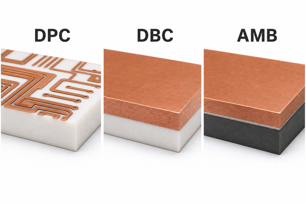
The ceramic grade must be compatible with the way copper or conductor paste is attached. Process choice controls conductor thickness, line width, via structure, bond strength and thermal cycling behavior.
| Process | Conductor structure | Typical material match | Design emphasis |
|---|---|---|---|
| DPC | Seed layer and plated copper, commonly tens of micrometers | Alumina and AlN | Fine lines, plated vias, compact signal and optical modules |
| DBC | Thick copper bonded through a controlled eutectic process | Alumina and AlN | High current, power spreading and robust copper areas |
| AMB | Thick copper joined by an active braze layer | Especially Si3N4; also selected advanced ceramics | High bond reliability and severe thermal cycling |
| Thick film | Screen-printed metal paste fired onto ceramic | Commonly Alumina | Resistors, heaters, hybrid circuits and economical conductor patterns |
DPC is not simply a thinner version of DBC, and AMB is not chosen only because it can carry current. Each process creates a different metal-ceramic interface. Ceramic circuit board material manufacturers must control ceramic lot properties, surface preparation, copper thickness, edge geometry and the symmetry of copper on both sides to limit warpage and interfacial stress.
Which Material Properties Matter Most in Ceramic PCB Design?
Thermal conductivity describes heat transport inside the ceramic, but it does not include solder, copper spreading, interfaces or the heat sink. CTE affects strain during temperature changes. A closer match to silicon can reduce stress, although package construction and solder compliance remain important.
Dielectric strength and volume resistivity govern insulation, while dielectric constant and loss tangent matter for RF transmission lines and resonant structures. These values depend on frequency, temperature and material grade. A single room-temperature value should not be used outside its test condition.
Flexural strength measures resistance to bending failure, while fracture toughness describes resistance to crack growth. Surface roughness, flatness, thickness tolerance and grain structure affect metallization, wire bonding, soldering and assembly alignment. The material datasheet and finished-board specification therefore need separate limits.
How Do Substrate Thickness and Copper Layout Affect Thermal Performance?
Through-thickness thermal resistance is approximately proportional to substrate thickness and inversely proportional to conductivity and heat-transfer area. Reducing the ceramic thickness can lower resistance, but it also reduces mechanical stiffness and voltage margin. Enlarging the copper area under a heat source spreads heat before it crosses the ceramic, reducing local temperature concentration.
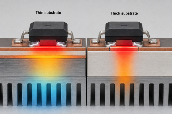
Copper balance also matters. A large thickness or coverage difference between the two sides can bend the board after bonding or during thermal cycling. Rounded copper corners, controlled copper-to-edge distance and gradual thickness transitions reduce stress concentration. Thermal simulation should include the actual die footprint, solder layer, copper geometry, ceramic thickness, attachment layer and heat sink rather than comparing only catalog conductivity.
Large ceramic circuit boards magnify flatness, handling and copper-balance risks because a small curvature across a long span can interfere with assembly contact or heat-sink attachment. Large formats may need additional tooling support, symmetric copper zones, controlled firing layout or subdivision into smaller modules. The awkward search phrase "large ceramic circuit board material" is therefore best understood as a size-dependent ceramic board design problem, not a separate material family.
Which Applications Fit Each Ceramic Circuit Board Material?
Material selection becomes clearer when the dominant load is identified. Alumina fits cost-controlled electronic modules that need insulation, temperature resistance and moderate heat spreading. AlN fits compact devices with high heat flux. Si3N4 fits modules exposed to strong vibration and repeated power cycling.
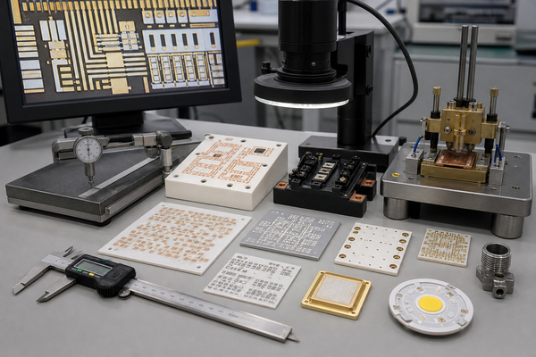
- LED and UV modules: Alumina for moderate power; AlN when optical density and junction temperature create a tighter thermal limit.
- Laser and optoelectronic modules: AlN for concentrated heat, with DPC when fine alignment features are required.
- RF and microwave circuits: high-purity Alumina or AlN selected by dielectric loss, surface finish and thermal load.
- Power modules and EV inverters: DBC AlN for high heat flow or AMB Si3N4 for severe cycling and mechanical reliability.
- Sensors, heaters and hybrid circuits: Alumina with thick-film conductors and printed resistive elements.
How Should Ceramic Circuit Board Material Be Selected?
Start with the device temperature limit and the complete thermal path. If FR4 or MCPCB can meet the target with adequate margin, ceramic may be unnecessary. If the ceramic is required, calculate the substrate resistance with realistic thickness and heat-source area, then compare Alumina and AlN before moving to more specialized materials.
Next, evaluate mechanical loading. Repeated power cycling, vibration and a large copper-to-ceramic CTE mismatch can make Si3N4 and AMB more suitable even when AlN offers higher conductivity. Then match conductor requirements: fine lines and vias point toward DPC, thick current paths toward DBC or AMB, and printed resistors or heaters toward thick film.
Finally, confirm frequency-dependent dielectric data, voltage spacing, surface finish, flatness, machining features and assembly temperature. A material name by itself is not a complete specification. The finished ceramic substrate PCB must satisfy thermal, electrical, mechanical and manufacturing limits at the same time.
FAQ About Ceramic Circuit Board Material?
Is FR4 a ceramic?
No. FR4 is a glass-fiber-reinforced epoxy laminate. Ceramic boards use fired inorganic substrates such as Alumina, AlN or Si3N4.
What is the most common ceramic PCB material?
Alumina is the most common because it combines mature processing, electrical insulation, stable supply and lower cost than AlN or Si3N4.
What Is the Best Ceramic Circuit Board Material?
There is no universal best material. Alumina is usually best for balanced cost and performance, AlN for concentrated heat transfer, and Si3N4 for fracture resistance and repeated thermal cycling.
Which ceramic PCB material has the highest thermal conductivity?
Among commonly selected non-toxic electronic substrates, AlN usually provides the highest conductivity. BeO can reach very high values but requires strict controls because damaged or machined material can create hazardous dust.
Is aluminum nitride always better than Alumina?
No. AlN is better when its higher thermal conductivity and closer CTE match solve a real system constraint. Alumina is often better when thermal demand is moderate and mature, economical processing is more important.
What Is a Multilayer Ceramic PCB?
A multilayer ceramic PCB uses stacked ceramic dielectric layers and internal conductors, commonly through LTCC or HTCC co-firing. Other ceramic constructions may use plated vias, double-sided circuits or assembled ceramic layers, but their process limits differ from conventional FR4 multilayers.
Conclusion
Ceramic circuit board material selection should connect Alumina, AlN or Si3N4 to the complete board construction. Alumina is the practical baseline, AlN is suited to concentrated heat flow, and Si3N4 is strongest where fracture resistance and thermal cycling dominate. DPC, DBC, AMB and thick-film processes then determine how the conductor system uses those material properties.
As a ceramic PCB manufacturer, BSTCeramicPCB supports Alumina, aluminum nitride and silicon nitride ceramic substrates with multiple metallization routes for electronic applications. For a technical discussion about material grade, substrate thickness, copper structure or process compatibility, contact sales@bstceramicpcb.com.
 Products
 About us
 Contact us



