


 HOME
HOME

-

Step-by-Step Guide to DPC PCB Design for Sensor Systems
2025 12,03 -
Ceramic PCBs Essential Benefits and Applications
2025 12,01 -
How Al2O3 DPC Ceramic Substrate PCB Enhances Heat Dissipation in Modern Electronics?
2025 11,28 -
How to Choose Between Ceramic, FR4, and Metal Core PCBs
2025 11,27 -
DPC Ceramic PCB Materials: Surprising Science Inside
2025 11,26 -
Wire bondable 2-layer Alumina substrates PCB | Bstceramic PCB
2025 09,22 -
Silicon Nitride Substrate, Silicon Nitride Ceramic Substrate Formula
2025 05,08 -
How to choose the appropriate substrate for ceramic circuit boards?
2023 11,16 -
Laser Cutting or Water Saw Cutting? How To Choose the Best Cutting Solution for Ceramic Circuit Boards
2023 11,13 -
Why Ceramic PCB Is So Expensive?
2023 11,10 -
Which Process Ceramic Circuit Board Is A Better Solution For Semiconductor Refrigerator Chips?
2023 11,06 -
Silicon Printing Circuit Boards For Advancing Electronics
2023 10,27 -
What is the Difference Between HTCC and LTCC Ceramic PCB
2023 10,06 -
What is the Difference Between 96% and 99% Aluminum Oxide in Ceramic PCBs?
2023 09,20 -
Why thick film ceramic PCB is good for oil level sensor in automotive industry?
2023 08,25 -
Statistical analysis of ceramic PCB application fields
2023 08,16 -
Notice of anti-static requirements for PCBA processing and production
2023 08,16 -
Silver Paste: The Best Conductor Material for Via Holes in Thick Film Ceramic Boards
2023 08,16 -
Testing Circuit Board Ceramic Diode Fuses: A Complete Guide
2023 08,07 -
Why DBC is replaced by DPC in ceramic PCB manufacturing?
2023 08,01 -
What is thick film ceramic PCB?
2023 08,02
Step-by-Step Guide to DPC PCB Design for Sensor Systems
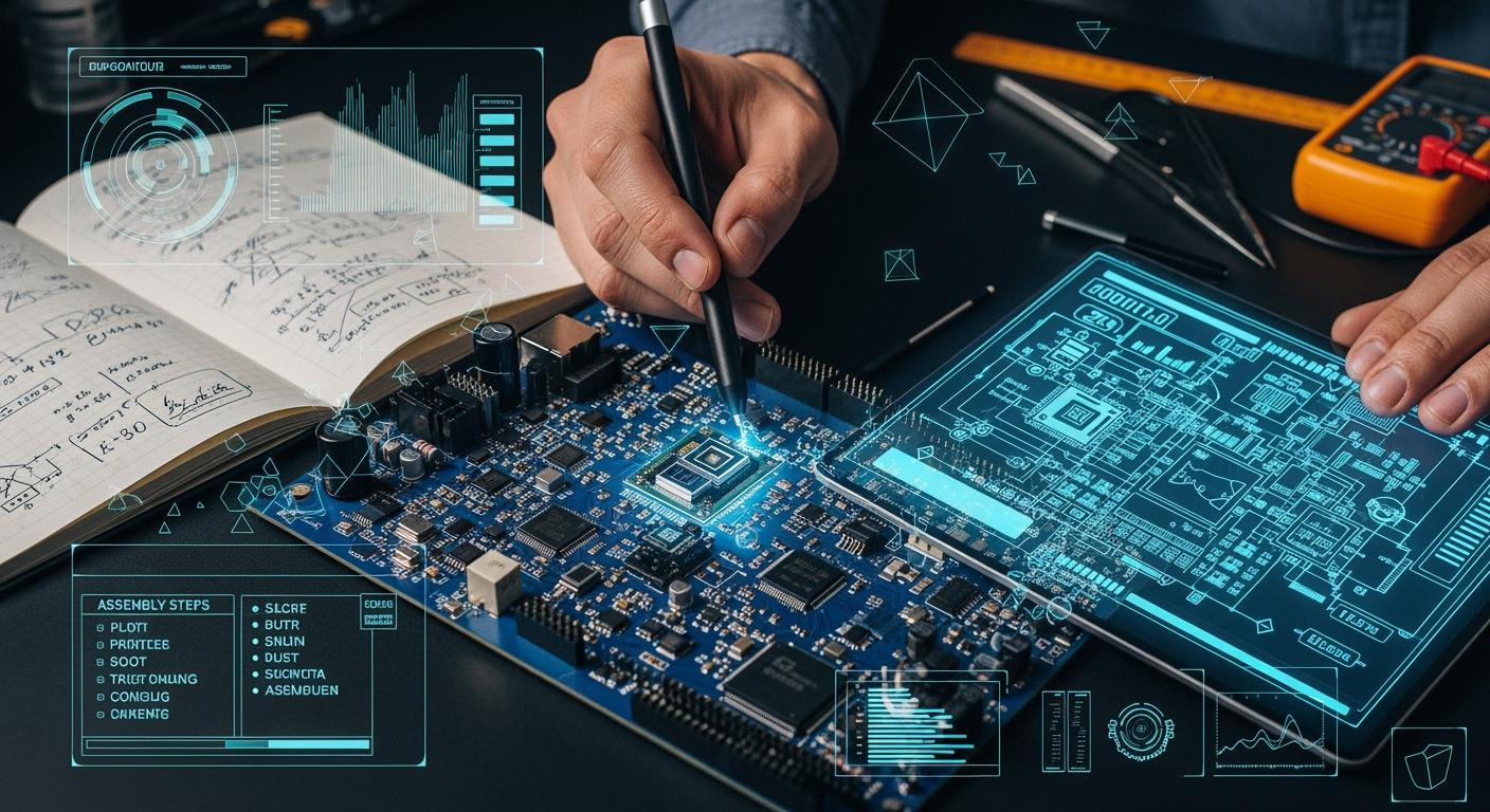
To create a DPC PCB For Sensor, follow simple steps. Ceramic boards are great for managing heat and reducing the size of your sensor system. Advanced sensors perform efficiently with a DPC PCB For Sensor because these boards distribute heat and support miniaturization. Careful planning, a smart layout, and selecting the best components are key to avoiding errors. Real-world issues like noise and stress matter, so consider them early when designing your DPC PCB For Sensor.
Key Takeaways
- DPC PCBs have ceramic boards that handle heat well. This lets sensor systems be smaller and work better. Careful planning and layout are very important. They help stop problems like noise and too much heat in your sensor design. Pick the right parts and communication protocols. This makes sure your sensors work well together. Use simulation tools to test your design before building it. This helps you find mistakes early and saves time. Good thermal management and placing parts in the right spots help your sensor system work better and last longer.
DPC PCB For Sensor Integration
DPC PCB Technology Overview
You can use DPC PCB For Sensor systems to help sensors work better in hard places. DPC means "Direct Plated Copper." This uses ceramic boards with copper on them. Ceramic boards handle heat better than plastic boards. You can make your sensor system smaller with ceramic boards. DPC PCB For Sensor designs let you put sensors close together. They do not get too hot.
Tip: Ceramic boards do not get damaged by water or chemicals. You can use them where regular boards might break.
Benefits for Sensor Systems
DPC PCB For Sensor systems have many good points. They keep sensors cool, even if they run for a long time. You can fit more sensors in a small area. You can use strong sensors, like MEMS or capacitive types. DPC PCB For Sensor boards handle heat and block electrical noise.
Some main benefits are:
- Better heat dissipation: Sensors do not get too hot.
- Miniaturization: You can make smaller devices.
- Advanced sensor compatibility: You can use new sensors that need steady heat.
- Improved reliability: Your sensor system lasts longer.
| Feature | DPC PCB For Sensor | Standard PCB |
|---|---|---|
| Heat Dissipation | Excellent | Moderate |
| Size Reduction | High | Low |
| Sensor Density | High | Medium |
| Environmental Tolerance | Strong | Weak |
Key Integration Considerations
You need to think about a few things when you design a DPC PCB For Sensor system. Pick the right ceramic for your board. Plan where each sensor goes to stop heat problems. Check how close sensors are so they do not mess each other up. Use shielding to block electrical noise.
Note: You can ask your PCB maker for help with ceramic choices and sensor spots. You can also send questions on the website.
Test your design with simulation tools before you build it. Use software to see if your sensors work well together. Make sure your design fits your needs, like temperature and size.
If you want to know more or need help with your DPC PCB For Sensor project, you can talk to experts on the website. You can send an email or fill out a form to get help.
Planning and Requirements
Define Sensor Objectives
Start your project by setting clear goals for your sensor system. Decide what you want your sensors to measure. You might need to track temperature, pressure, or movement. Write down the main tasks for each sensor. Make a list of the features you need. Think about how fast your sensors must respond and how accurate they should be.
Tip: Use a table to compare sensor options. This helps you pick the best one for your needs.
| Sensor Type | Measurement | Speed | Accuracy | Size |
|---|---|---|---|---|
| MEMS | Motion | Fast | High | Small |
| Capacitive | Humidity | Medium | Medium | Small |
| Thermal | Temperature | Slow | High | Large |
Environmental & Mechanical Needs
Check where you will use your sensor system. Some places get very hot or cold. Others have lots of dust or water. Make sure your sensors and board can handle these conditions. Ceramic boards in a DPC PCB For Sensor system work well in tough spots. They resist heat, moisture, and chemicals. Plan for shocks and vibration if your device moves a lot.
List the mechanical needs for your project. Think about size, weight, and how you will mount the board. If you want a small device, choose sensors that fit tight spaces. MEMS sensors and capacitive sensors help you shrink your design.
Communication Protocols
Pick how your sensors will talk to the rest of your system. You can use I2C, SPI, or UART. Some sensors need fast data transfer. Others work with slower connections. Write down the protocol for each sensor. Make sure your board supports these choices.
Note: If you need help with protocol selection or board design, send a message through the website form or email. Experts can guide you.
Plan your system with care. Good planning helps you avoid problems later. You will save time and money if you set clear goals and check all needs before you start building.
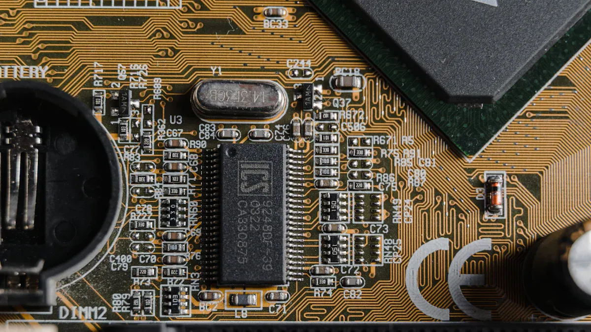
Schematic Design for Sensors
Sensor Circuit Basics
First, draw the main parts of your sensor system. Each sensor needs power and ground. Each sensor also needs a way to send signals. Put your sensors on the diagram before anything else. Add the microcontroller or processor next. This part reads the sensor data. Connect each sensor to the correct pins. Label every wire and part clearly. This helps you and your team avoid mistakes.
Tip: Use easy symbols for each sensor. This makes your schematic simple to read.
Signal Conditioning
Sensors often give weak or noisy signals. You need to clean up these signals first. Add resistors, capacitors, and amplifiers to your schematic. These parts help filter noise and make signals stronger. For example, an op-amp can make a small voltage bigger.
- Common signal conditioning parts:
- Resistors (R)
- Capacitors (C)
- Op-amps
- Filters
| Signal Issue | Solution Part | Example Use |
|---|---|---|
| Noise | Capacitor | Smoothing input |
| Weak Signal | Op-amp | Amplifying |
| Drift | Resistor | Stabilizing |
DPC Compatibility
When you design for DPC PCBs, check your schematic for ceramic board needs. DPC boards handle heat well. Keep high-power parts away from sensitive sensors. Pick parts that work at higher temperatures. Make sure your signal paths are short. This helps reduce noise.
Note: If you have questions about DPC compatibility, send a message through the website form or email. Experts can help you pick the right parts.
You can use EDA tools like Altium Designer to check your schematic. These tools help you find errors before you build your board. Careful design now saves time and money later.
DPC PCB For Sensor Layout

Layer Stackup & Routing
You build a strong sensor system by choosing the right layer stackup. DPC PCB For Sensor designs use ceramic layers with copper. You can add more layers to fit extra sensors and circuits. High-Density Interconnect (HDI) technology helps you place thin lines and small vias. These features let you route signals in tight spaces. Microvias connect layers with tiny holes made by lasers. You save space and keep your board small.
You must route signals carefully. Place high-speed lines away from noisy parts. Keep power and ground lines short. This reduces electrical noise. You can use ground planes to block interference. If you work with capacitive or MEMS sensors, keep their signal paths straight. Avoid sharp turns in traces. This helps your sensors work better.
Tip: Use simulation tools to check your routing before you build the board. You can find problems early and fix them.
Sensor Placement
You decide where each sensor goes on the board. Good placement helps your sensors work well and last longer. Put heat-sensitive sensors away from hot parts. Place MEMS sensors where they get less vibration. You can group similar sensors together. This makes routing easier and reduces noise.
You must think about electromagnetic interference (EMI) and crosstalk. Keep sensors that pick up weak signals away from strong signal lines. Use shielding if you need to block noise. You can add guard traces around sensitive sensors. This stops unwanted signals from reaching them.
| Sensor Type | Best Placement Area | EMI Risk | Heat Risk |
|---|---|---|---|
| MEMS | Low vibration zone | Medium | Low |
| Capacitive | Far from power lines | High | Low |
| Thermal | Near heat source | Low | High |
Note: If you need help with sensor placement, you can send questions through the website form or email. Experts can help you plan your layout.
Miniaturization Techniques
You can make your sensor system smaller by using smart layout methods. HDI PCB technology lets you use thin lines and tiny vias. Microvia design uses laser-drilled holes to connect layers. This frees up space for more sensors. You can embed components inside the board layers. This reduces the footprint and keeps your device compact.
Try these miniaturization techniques:
- Use HDI PCB to fit more sensors in a small area.
- Add microvias for efficient multi-layer connections.
- Embed components within board layers to save space.
- Optimize placement to avoid wasted board area.
- Choose small form factor solutions for tight spaces.
You keep your sensor system small and powerful by using these methods. You can fit advanced sensors into compact devices. You also improve heat dissipation and reliability.
Tip: If you want to learn more about miniaturization, you can contact experts through the website. You can send an email or fill out a form for advice.
You improve your sensor system by planning your layout with care. You use the right stackup, place sensors wisely, and apply miniaturization techniques. You solve real-world problems like heat and noise. You build a reliable DPC PCB For Sensor system that fits your needs.
DPC Circuit Board Component Selection
Sensor & Support Parts
You need to choose sensors and support parts that match your system goals. Each part must work well with the DPC PCB and fit your design. Look at the main criteria before you select any component. The table below shows what you should consider:
| Criteria | Explanation |
|---|---|
| Thermal Management | Use thermal vias or heat-dissipating materials to handle heat in small designs. |
| Signal Integrity | Keep signals clean by controlling impedance and using shielding to stop crosstalk and EMI. |
| Manufacturing Complexity | Pick parts that do not make the board too hard or costly to build. |
| Power Efficiency | Choose low-power parts to help your device last longer on battery. |
You can compare different sensors and support chips using these points. This helps you find the best fit for your project. If you have questions about which parts to use, you can send an inquiry through the website form or email.
Placement & Accessibility
You must place each part where it works best and is easy to reach. Put sensors where they can measure correctly and avoid heat or noise. Place support chips close to the sensors they help. This keeps signal paths short and strong. Make sure you can reach test points and connectors for repairs or updates. Good placement makes your board easier to build and fix.
Tip: Group similar parts together. This makes routing easier and helps you spot problems during testing.
Thermal Management
Small boards with many parts can get hot fast. You need to control heat to keep your system safe. Try these strategies:
- Add thermal vias under hot parts to move heat away.
- Use heat-dissipating materials in your board stackup.
- Keep the temperature of each part below 85°C for safety.
- Spread out high-power parts to avoid hot spots.
You protect your sensors and make your system last longer by managing heat well. If you need help with thermal design, you can ask experts through the website.
Signal & Power Integrity
High-Speed Routing
You need to route high-speed signals with care. Fast signals can cause problems if you do not plan the path. Keep traces short and straight. Use controlled impedance to help signals stay strong. Avoid sharp corners because they can reflect signals and create noise. Place high-speed lines away from power circuits. You can use differential pairs for signals like USB or LVDS. This helps reduce interference.
Tip: Use simulation tools to check your routing before you build. You can find signal problems early and fix them.
| Routing Rule | Why It Matters |
|---|---|
| Short, straight lines | Less signal loss |
| Controlled impedance | Stable signal quality |
| Avoid sharp corners | Lower signal reflection |
Power Distribution
You must give each sensor and chip the right amount of power. Use wide traces for power lines. This lowers resistance and keeps voltage steady. Place decoupling capacitors close to each chip. These parts help filter noise and keep power clean. Spread out power sources to avoid hot spots. You can use multiple power planes in your board. This helps deliver power evenly.
- Place capacitors near sensors.
- Use wide traces for main power.
- Check voltage at each sensor.
If you need help with power planning, you can send questions through the website form or email.
Grounding & Noise Control
Good grounding keeps your sensor system safe from noise. Use a solid ground plane under your board. Connect all ground pins to this plane. Keep ground paths short. This helps block unwanted signals. You can add shielding around sensitive sensors. Guard traces also help stop noise from reaching important parts.
Note: If you see noise in your signals, check your grounding first. You can ask experts for advice by sending a message on the website.
You improve your sensor system by following these steps. You keep signals strong, power steady, and noise low. Your DPC PCB for sensors works better and lasts longer.
Ceramic PCB Prototyping and Testing
DFM for DPC PCB
When you start making a prototype, you focus on Design for Manufacturability (DFM). DFM helps you stop mistakes that slow down building or make things cost more. You check your sensor layout to see if each part fits on the ceramic board. You look for spots where heat could build up. You use thermal vias and special materials to move heat away from sensors that are sensitive. You also plan for tight spaces and make sure your design does not get too crowded.
Tip: You can ask your PCB manufacturer for help with DFM. They can help you pick the right ceramic and give ideas to make your design better.
Assembly & Build
You face many problems when you put together and build your DPC PCB for sensors. Smaller boards make more heat, so you need good thermal management. Tighter layouts can cause signal problems like crosstalk and EMI. You must control impedance and use shielding to keep signals clean. Microvia design and putting parts inside the board make building harder and can cost more. You also need to pick low-power parts and plan smart layouts for battery-powered sensors.
| Challenge | Description |
|---|---|
| Thermal Management | Smaller boards make more heat; use thermal vias and heat-dissipating materials. |
| Signal Integrity | Tighter layouts risk crosstalk and EMI; control impedance and use shielding. |
| Manufacturing Complexity | Microvia design and putting parts inside the board make building harder and cost more. |
| Power Efficiency | Low-power parts and smart layouts help battery sensors last longer. |
Note: If you have trouble during assembly, you can send questions through the website form or email. Experts can help you fix these problems.
Simulation & Validation
You use simulation tools to test your design before you build the board. COMSOL helps you model sensor accuracy and guess how your system will work in real life. You check for heat problems, signal loss, and noise. You use EDA tools like Altium Designer to check your schematic and layout. These tools let you test capacitive and inductive sensors and make sure they work as planned.
- You run simulations to find mistakes early.
- You check sensor performance with modeling software.
- You change your design based on test results.
Tip: You can contact experts through the website for help with simulation and validation. They can show you the best tools and ways to test.
You make your sensor system better by testing and checking each step. Careful prototyping helps you build a strong DPC PCB for sensors.
Troubleshooting Challenges
Manufacturing Defects
You can have problems with your DPC PCB when making it. These problems can stop your sensor system from working right. Some common defects are bad solder joints, parts that are not lined up, or cracks in the ceramic board. You should check your board for these problems after you put it together.
- Visual Inspection: Check for missing or wrong parts.
- X-ray Testing: Find hidden solder problems or cracks.
- Continuity Testing: Make sure all connections work well.
Tip: Work with your PCB maker. They can help you find and fix problems early. If you see something wrong, send a picture or question through the website or email.
Sensor Communication Issues
Sometimes, sensors do not send data the way you want. You might get missing readings or strange numbers. These problems often happen because of loose wires, wrong protocol settings, or broken traces.
| Issue | Possible Cause | Quick Fix |
|---|---|---|
| No data | Loose connector | Reseat or change cable |
| Wrong values | Protocol mismatch | Check sensor settings |
| Intermittent signals | Broken trace | Look at and fix trace |
You can use a logic analyzer to check your data lines. Make sure your microcontroller uses the right protocol, like I2C or SPI. Double-check sensor addresses and wiring.
Note: If you cannot fix a communication problem, send your question to the website support team. They can help you solve it.
Signal & Power Problems
Signal and power problems can make your sensor system not work. You may see noise, weak signals, or sensors that do not turn on. These problems often come from bad grounding, thin power lines, or missing capacitors.
- Use a multimeter to check voltage at each sensor.
- Add decoupling capacitors near power pins.
- Keep ground paths short and strong.
If you see noise in your signals, move sensitive sensors away from power lines. Shielding and guard traces can help too.
Callout: Careful troubleshooting saves you time and money. If you need help, reach out through the website or email for expert advice.
You can design a strong DPC PCB for sensor systems by following clear steps. Start with careful planning. Focus on smart layout and thorough testing.
- Work closely with your PCB manufacturer for better results.
- Use simulation tools to check your design before building.
Keep learning about new DPC and sensor technologies. If you need help, send your questions through the website form or email. Your next project can be even better!
 Products
 About us
 Contact us