






















































 HOME


-

Ceramic PCB for Humanoid Robot joint actuators
2026 04,07 -
LTCC PCB Surprises: What Most People Miss
2025 12,09 -
Step-by-Step Guide to DPC PCB Design for Sensor Systems
2025 12,03 -
Ceramic PCBs Essential Benefits and Applications
2025 12,01 -
How Al2O3 DPC Ceramic Substrate PCB Enhances Heat Dissipation in Modern Electronics?
2025 11,28 -
How to Choose Between Ceramic, FR4, and Metal Core PCBs
2025 11,27 -
DPC Ceramic PCB Materials: Surprising Science Inside
2025 11,26 -
Wire bondable 2-layer Alumina substrates PCB | Bstceramic PCB
2025 09,22 -
Silicon Nitride Substrate, Silicon Nitride Ceramic Substrate Formula
2025 05,08 -
What is thick film ceramic PCB?
2023 08,02
How Should Ceramic Copper Adhesion Strength Be Tested and Specified?
Published:
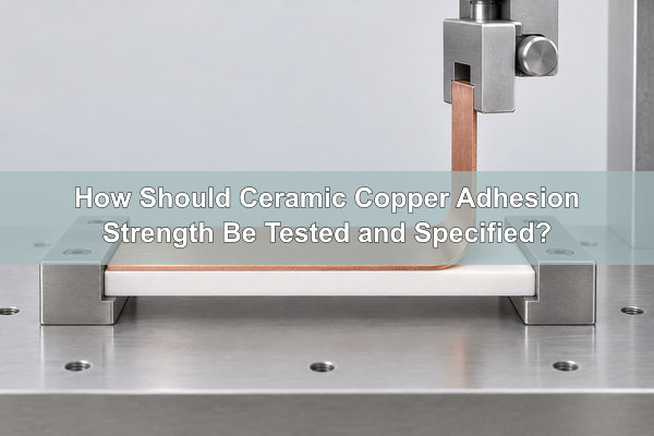
Ceramic copper adhesion strength describes how a copper layer or copper foil remains joined to a ceramic substrate under a defined load. It is not one universal material constant. A peel result in N/mm, a pull result in MPa, and a shear result in MPa use different specimens and stress fields, so the number is meaningful only with the test method, copper thickness, geometry, conditioning, and fracture location.
What Does Ceramic Copper Adhesion Strength Mean?
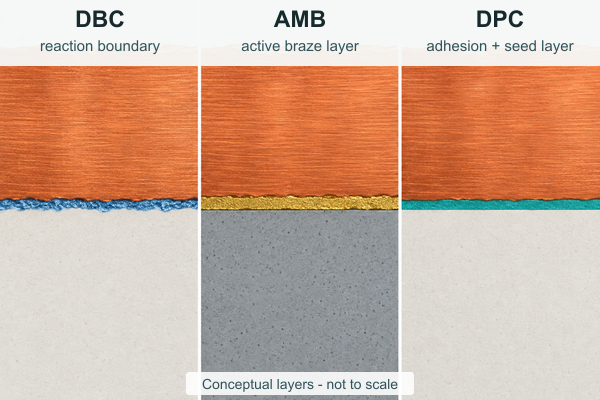
Ceramic copper adhesion strength is the measured resistance of a copper-ceramic structure to a specified separation load. The structure may be bonded copper foil in DBC, brazed copper foil in AMB, or plated copper on a deposited adhesion layer in DPC. Each route creates a different interface and therefore needs a matching test specimen.
The reported value belongs to the complete specimen, not only to an ideal mathematical interface. Copper deformation, braze thickness, reaction layers, ceramic surface condition, pad geometry, and the loading fixture can all influence the result. A useful specification therefore names both the value and the conditions that produced it.
Why Can’t N/mm and MPa Be Compared Directly?
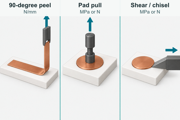
N/mm is normally a force per strip width used for peel testing, while MPa is force divided by a loaded area in a pull or shear test. These units do not describe the same stress state. Converting them arithmetically does not create an equivalent test because the specimen bends, rotates, and concentrates stress differently.
A peel test also spends energy bending and plastically deforming the copper strip. A pull or shear test places more dependence on pad size, fixture alignment, loading height, and stress concentration at the pad edge. Reported ceramic copper adhesion strengths should therefore be compared only when the test configuration and specimen construction are sufficiently similar.
Which Test Method Fits the Copper-Ceramic Structure?
The test should match the conductor geometry and the failure risk that matters in the finished assembly.
| Test approach | Common output | Useful for | Conditions that must accompany the result |
|---|---|---|---|
| 90-degree or 180-degree peel | N/mm | Bonded or brazed copper foil that can be formed into a peel strip | Peel angle, speed, strip width, copper thickness, bend preparation, temperature and conditioning |
| Stud pull or pad pull | MPa or N | Plated copper pads, DPC coupons, or localized metallization | Pad area, stud attachment method, loading alignment, pull rate, ceramic thickness and failure location |
| Shear or chisel test | MPa or N | Small pads, metallized features, or comparative process monitoring | Tool height, direction, speed, pad dimensions, edge clearance and fixture support |
| Thermal cycling followed by a mechanical test | Retained N/mm, MPa, or percentage | Reliability comparison after thermo-mechanical exposure | Temperature limits, dwell, ramp, cycle count, atmosphere, sample geometry and post-test method |
A drawing that states only “high adhesion” cannot be inspected consistently. A drawing that states the method and specimen conditions gives the manufacturer and customer the same acceptance target.
How Do Copper Thickness and Test Geometry Change the Result?
Copper thickness affects both the actual structure and the mechanics of the test. In a peel test, thicker or harder copper requires more force to bend. Part of the measured load can therefore come from copper deformation rather than separation at the copper-ceramic interface. Peel angle, bend radius, loading speed, and strip width also change the force path.
Pad tests have a different geometry problem. The nominal stress is calculated from pad area, but the real stress is usually highest at an edge. A small change in pad shape, attachment fillet, loading height, or fixture alignment can change where fracture begins. When comparing suppliers or process lots, use the same coupon design and procedure rather than comparing isolated catalog numbers.
What Does the Fracture Surface Reveal?
The fracture surface shows what actually limited the specimen. A numerical result without a failure-mode record can conceal a weak interface or, conversely, underestimate an interface that remained intact while the ceramic fractured.
- Interface separation: a relatively clean boundary between the metallization system and ceramic indicates that the joint itself controlled failure.
- Reaction-layer or braze failure: residue on both sides may indicate fracture within an intermediate layer rather than at either parent material.
- Copper cohesive or attachment failure: torn copper, failed solder, adhesive, or stud attachment means the test may not have reached the ceramic interface limit.
- Ceramic breakout: ceramic remaining on the copper indicates that fracture propagated through the substrate near the interface. The measured value is then a structural failure value, not a pure interface adhesion value.
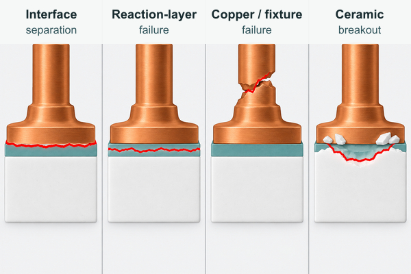
Record the fracture category, location, and approximate affected area for every tested specimen. Cross-sections or microscopy may be needed when visual inspection cannot distinguish a thin reaction-layer failure from true interface separation.
How Does DBC Form Its Copper-Ceramic Bond?
DBC joins copper foil to an oxide-compatible ceramic surface through a controlled high-temperature process involving copper, oxygen, and interfacial reaction. The result is not an organic adhesive layer. Surface cleanliness, oxygen control, temperature profile, ceramic condition, and cooling all affect whether the bonded area is continuous.
For a DBC ceramic circuit used in automotive components, bond acceptance should be coordinated with copper thickness, ceramic material, pattern geometry, and the expected thermal cycle. A coupon with broad copper coverage does not reproduce every stress concentration created by narrow traces and etched corners.
How Does AMB Build a Reactive Interface?
AMB uses an active braze system so that reactive elements can wet and join copper to ceramics that are difficult to bond directly. The reaction products, braze-layer continuity, local voids, thermal history, and residual stress all influence the joint. Strong initial peel performance is useful, but it does not by itself prove module life under repeated power or temperature cycling.
Our AMB ceramic substrate for IGBT power modules is relevant when heavy copper and demanding thermo-mechanical reliability are central requirements. The manufacturing specification should still define the ceramic, copper thickness, circuit geometry, test method, aging condition, and failure reporting instead of relying on the word “AMB” as a complete strength specification.
How Does DPC Create Adhesion with Thin Seed Layers?
DPC typically begins with a thin adhesion or barrier system deposited on a cleaned ceramic surface, followed by a copper seed layer and electroplated copper build. Surface contamination, deposition continuity, adhesion-layer chemistry, plated stress, and thermal exposure can affect the completed interface.
This structure is better suited to pull or shear coupons when the plated copper is too thin or too finely patterned to form a representative peel strip. Our alumina DPC ceramic substrate for LED circuits demonstrates the type of plated ceramic circuit in which fine geometry, copper build, and interface control must be evaluated together.
Which Layout Features Increase Edge Stress?
Copper edges are common initiation sites because the stiffness changes abruptly where metal coverage ends. Thick copper, sharp internal corners, narrow neck-downs, isolated small islands, copper close to the ceramic edge, and strongly unbalanced top-to-bottom coverage can increase local stress during cooling or thermal cycling.
Design review should therefore include copper corner radii, etch compensation, ceramic edge distance, pad transitions, copper balance, ceramic thickness, and support during assembly. A process coupon can monitor production consistency, but a coupon cannot replace review of the actual circuit geometry.
How Should Thermal Aging and Cycling Be Included?
Initial adhesion verifies the as-built interface; retained adhesion after exposure tests a different question. Repeated expansion mismatch can initiate cracks at copper edges, within a braze or reaction layer, or in the ceramic. High-temperature storage, assembly reflow, thermal shock, and power cycling also impose different time-temperature histories.
Specify the exposure that represents the product risk, then repeat the same mechanical test used for the initial baseline. Record any change in fracture location as well as the numerical retention. A stable value with a new ceramic-cracking mode is not automatically equivalent to an unchanged interface.
What Should the Drawing and Acceptance Plan Specify?
A reproducible copper-ceramic adhesion requirement should include:
- ceramic material, grade, thickness, and surface condition;
- metallization route such as DBC, AMB, or DPC;
- copper thickness, temper where relevant, and coupon geometry;
- test method, peel angle or loading direction, speed, and fixture details;
- sample location, quantity, conditioning, and test temperature;
- minimum acceptance value and the required statistical treatment;
- permitted and prohibited fracture modes;
- aging or cycling conditions and the required retained result;
- reporting requirements for force curves, photographs, microscopy, or cross-sections;
- design or process changes that require requalification.
Do not copy a threshold from another technology without copying its specimen and method. A DBC peel requirement cannot automatically qualify a DPC pull coupon, and an AMB value measured on one copper thickness cannot be transferred to another construction without review.
How Do We Review a Copper-Ceramic Adhesion Requirement?
We first identify whether the customer’s risk is foil delamination, plated-pad lift, ceramic cracking, or loss of strength after thermal exposure. We then review the ceramic, copper construction, artwork, test coupon, loading method, and acceptance evidence as one package. That keeps the test tied to the product instead of treating adhesion as an isolated catalog property.
Send the drawing, Gerber data, ceramic and copper specification, application temperature profile, assembly process, sample quantity, and proposed acceptance method to sales@bstceramicpcb.com. We can review whether DBC, AMB, or DPC is the appropriate manufacturing route and identify which test details are still missing before quotation. A useful ceramic copper adhesion strength requirement is one that both parties can reproduce and trace to a defined failure risk.
 Products
 About us
 Contact us



