






















































 HOME
HOME


-

Ceramic PCB for Humanoid Robot joint actuators
2026 04,07 -
LTCC PCB Surprises: What Most People Miss
2025 12,09 -
Step-by-Step Guide to DPC PCB Design for Sensor Systems
2025 12,03 -
Ceramic PCBs Essential Benefits and Applications
2025 12,01 -
How Al2O3 DPC Ceramic Substrate PCB Enhances Heat Dissipation in Modern Electronics?
2025 11,28 -
How to Choose Between Ceramic, FR4, and Metal Core PCBs
2025 11,27 -
DPC Ceramic PCB Materials: Surprising Science Inside
2025 11,26 -
Wire bondable 2-layer Alumina substrates PCB | Bstceramic PCB
2025 09,22 -
Silicon Nitride Substrate, Silicon Nitride Ceramic Substrate Formula
2025 05,08 -
What is thick film ceramic PCB?
2023 08,02
Ceramic PCB vs FR4 PCB: Thermal, Electrical, Cost and Design Comparison
Published:
Ceramic PCB vs FR4 PCB is a choice between an inorganic insulating substrate built for heat and stability and a glass-reinforced epoxy laminate built for routing flexibility, production scale and cost control. Ceramic is usually the stronger option when heat must pass through the electrically insulating board, while FR4 remains the practical default for most multilayer control, digital and mixed-signal assemblies. The correct decision depends on the complete thermal path, voltage, frequency, layer count, mechanical loading and production target.
What Is the Main Difference Between Ceramic PCB and FR4 PCB?
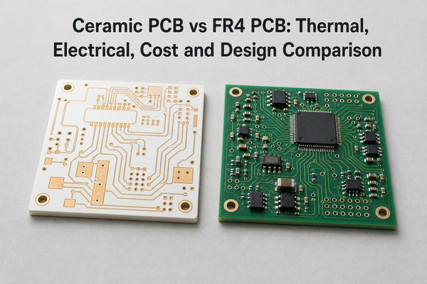
The main difference is the substrate under the copper circuit. A ceramic PCB uses alumina, aluminum nitride, silicon nitride or another engineered ceramic. An FR4 PCB uses woven glass fabric bonded with flame-retardant epoxy resin.
That material change affects almost every downstream decision. Ceramic can combine electrical insulation with much higher through-substrate heat transfer, low moisture uptake and dimensional stability. FR4 is easier to laminate, drill, plate and route into complex multilayer structures. It is also more tolerant of board flex and impact.
| Selection factor | Ceramic PCB | FR4 PCB |
|---|---|---|
| Main advantage | Heat transfer through an insulating substrate | Mature multilayer routing at lower cost |
| Common substrate | Al2O3, AlN, Si3N4 | Glass-reinforced epoxy |
| Mechanical behavior | Hard, rigid and brittle | Tougher and more forgiving |
| Typical architecture | Simple power substrate or specialized ceramic multilayer | Single-sided through high-layer-count PCB |
| Best starting point | High heat flux, high voltage isolation, direct die or stable RF module | Control, digital, analog and cost-sensitive electronics |
Neither material is universally better. If a heat sink, copper planes, thermal vias and airflow can control junction temperature, FR4 may meet the requirement with less manufacturing risk. If the PCB substrate itself must be a low-resistance heat path while maintaining isolation, ceramic becomes much more valuable.
How Do Their Material Structures Compare?
FR4 is a composite laminate. Copper foil is bonded to cores and prepregs, then multilayer panels are drilled, plated, imaged and etched. Designers can combine different copper weights, controlled-impedance layers, blind or buried vias and sequential lamination within a mature fabrication ecosystem.
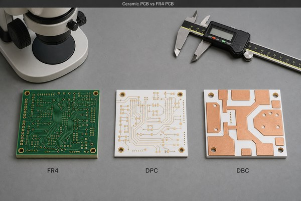
A ceramic circuit board starts with a sintered ceramic plate or co-fired ceramic layers. The circuit can be formed by thick film, thin film, direct plated copper (DPC), direct bonded copper (DBC) or active metal brazing (AMB). Each process changes the available copper thickness, line width, via method, bonding strength and thermal-cycling behavior.
This means “ceramic PCB” is not one specification. Alumina with thin-film metallization and AlN with thick DBC copper solve different problems. Material, metallization and copper structure must be selected together.
Ceramic PCB vs FR4 PCB Thermal Conductivity
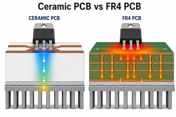
Ceramic substrates transfer heat far more effectively than standard FR4, but bulk thermal conductivity is only one part of the thermal design. Standard FR4 is commonly around 0.2-0.4 W/mK. Electronic-grade alumina is often about 20-35 W/mK, while common AlN grades may be roughly 140-180 W/mK; higher-performance grades are also available. Exact values depend on composition, purity, temperature and supplier data.
| Material | Typical bulk thermal conductivity | Practical implication |
|---|---|---|
| Standard FR4 | 0.2-0.4 W/mK | Heat usually needs copper spreading, vias and an external heat path |
| Alumina ceramic | 20-35 W/mK | Balanced ceramic option for many LED, sensor and power circuits |
| Aluminum nitride | 140-180 W/mK for common grades | Useful when high heat flux must cross an insulating substrate |
The highest W/mK value does not automatically produce the lowest component temperature. Total thermal resistance also includes the die attach, solder layer, copper geometry, substrate thickness, interface material, contact area and heat sink. A thin alumina substrate with a well-designed interface can outperform a thicker high-conductivity board with poor contact.
High-Tg FR4 should not be confused with high-thermal-conductivity material. A higher Tg improves laminate stability when temperature rises, especially during assembly and thermal excursions, but it does not remove the through-thickness heat-transfer bottleneck.
How Do Electrical Insulation and Signal Performance Compare?
Both ceramic and FR4 can provide electrical insulation, but their dielectric behavior is different. FR4 is adequate for a wide range of digital, analog and power-control boards. Its dielectric constant and loss vary with resin system, glass style, frequency, moisture and temperature, so a specific laminate data sheet is required for controlled high-speed or RF designs.
Alumina and AlN typically have higher dielectric constants than standard FR4, but many ceramic grades offer stable properties and low dielectric loss. This can benefit compact RF power modules, filters, sensors and packages. It does not mean every ceramic is better than every RF laminate. Low-loss PTFE, hydrocarbon-ceramic and other microwave materials may be more suitable when the main requirement is low insertion loss over a defined frequency band.
For high-voltage designs, dielectric strength must be evaluated with substrate thickness, metallization spacing, edge distance, surface condition and environmental contamination. A strong material data-sheet value cannot compensate for inadequate creepage or a damaged ceramic edge.
How Do CTE, Rigidity and Mechanical Reliability Compare?
Ceramic substrates usually have lower coefficients of thermal expansion than FR4 and can be closer to semiconductor materials. This reduces differential movement in direct-die, power-module and repeated thermal-cycling applications. The benefit is most useful when the ceramic, copper, solder, die attach and package are designed as one mechanical stack.
Mechanical terminology matters. Ceramic is hard and rigid, but it is also brittle. It resists bending and maintains dimensional stability, yet edge chips, microcracks, point loading or board flex can cause sudden fracture. FR4 is less rigid but tougher, so it generally tolerates handling, vibration, screw loading and enclosure flex better.
For ceramic assemblies, reliability review should include edge quality, copper balance, substrate thickness, unsupported span, fixture pressure and component mass. Silicon nitride may be considered when fracture toughness and power cycling are more important than the lower cost of alumina.
Which Supports More Layers, Vias and Routing Density?
FR4 is usually the better platform for dense multilayer routing. Conventional plated through holes, laser microvias, buried vias, sequential lamination and controlled impedance are widely available. This makes FR4 suitable for processors, memory, communications, control logic and other interconnect-heavy designs.
Ceramic circuits can be multilayer, but the manufacturing route is different. LTCC and HTCC can integrate internal conductors, vias and passive functions, while DPC, DBC, AMB, thin-film and thick-film boards are commonly simpler structures. Moving an existing eight-layer FR4 layout directly onto a ceramic plate is rarely a material-only substitution.
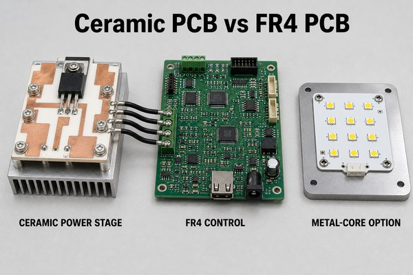
When power and control functions are mixed, splitting the design is often cleaner: use ceramic under the heat-generating power stage and use FR4 for connectors, control, isolation feedback and dense routing.
How Do Manufacturing and Assembly Requirements Differ?
FR4 uses mature subtractive PCB processes and is comparatively forgiving during depanelization, drilling and assembly. Ceramic requires process-specific metallization, controlled cutting and careful mechanical support.
For fine lines and compact circuits, a DPC ceramic PCB can provide plated copper features and precision patterning. For heavier copper and high-current power paths, a custom DBC ceramic substrate uses a different bonding structure. In power modules exposed to demanding thermal cycling, a double-sided AMB ceramic PCB may be evaluated for copper-to-ceramic bond reliability.
Assembly risks also differ:
- Ceramic panels need support during printing, placement, reflow and test to prevent bending loads.
- Large copper areas should be balanced to reduce bow and stress.
- Solder paste volume and reflow profile must suit the copper mass and component termination.
- Mechanical fasteners, clamps and heat-sink pressure require controlled flatness and load distribution.
- FR4 designs still need attention to z-axis expansion, plated-hole reliability and moisture, especially with thick or high-layer-count boards.
Prototype validation should focus on the actual failure mechanism: thermal imaging for hot spots, isolation testing for voltage stress, cross-sections for interfaces, warpage measurement, and thermal cycling when lifetime depends on material mismatch.
Ceramic PCB vs FR4 PCB Cost and Lead-Time Factors
Ceramic PCB normally costs more and requires a more specialized production route than FR4. A useful comparison should not rely on a fixed multiplier because board area, substrate type, copper thickness, process, tolerances, yield, test requirements and quantity can change the result substantially.
| Cost driver | Ceramic PCB impact | FR4 PCB impact |
|---|---|---|
| Base material | Alumina, AlN and Si3N4 have different price levels | Broad laminate supply and standardized grades |
| Circuit process | DPC, DBC, AMB, thin film and thick film use different tooling | Standard imaging, etching, lamination and plating are highly scaled |
| Mechanical features | Laser cutting, edge quality and brittle handling affect yield | Routing and drilling are mature and economical |
| Copper | Heavy bonded copper changes stress and process window | Copper weight affects etching and plating but is widely supported |
| Tolerance and test | Flatness, adhesion and thermal cycling can add inspection | HDI, impedance and reliability tests can also add cost |
Over-specification is a common source of unnecessary ceramic cost. Selecting AlN when alumina meets the thermal model, specifying tighter flatness than the assembly needs, or using bonded heavy copper for a fine-signal circuit can increase price without improving field performance.
When Should You Choose a Ceramic PCB?
Choose ceramic when the design needs a combination of heat transfer, electrical isolation and dimensional stability that is difficult to achieve with FR4.
Typical cases include:
- power semiconductor and direct-die substrates
- high-power LEDs and laser diode submounts
- IGBT, MOSFET, SiC and GaN power modules
- compact RF power amplifiers and microwave packages
- automotive traction, charging and power-conversion modules
- medical, industrial and aerospace circuits with demanding thermal stability
The strongest trigger is not simply a high ambient temperature. It is a thermal or electrical requirement that depends on the substrate: concentrated heat must cross the board, the package needs a close CTE match, or the circuit needs stable insulation and geometry under repeated temperature change.
When Is FR4 the Better Choice?
FR4 is the better choice when routing density, mechanical toughness, fast iteration and cost matter more than heat conduction through the dielectric.
Use FR4 as the default for control boards, communication interfaces, processors, power-supply control sections, consumer electronics and industrial logic. It also remains suitable for many moderate-power designs when copper planes, thermal vias, heat sinks, airflow or an enclosure provide an adequate heat path.
FR4 is often preferable when the board needs many signal layers, large dimensions, connectors exposed to insertion force, or a structure that can tolerate some flex. Choosing ceramic for these cases can add cost and handling risk without solving a real constraint.
Is Metal-Core PCB or a Hybrid Assembly a Better Alternative?
Metal-core PCB can be the practical middle option when heat dissipation is more important than complex multilayer routing, but the design does not require the full electrical, thermal or environmental performance of ceramic. Aluminum-core boards are common in LED and moderate-power products because the metal spreads heat at lower cost than many ceramic structures.
The limiting element in a metal-core PCB is often the thin dielectric between copper and metal. Its thickness and conductivity determine both isolation and thermal resistance. Ceramic removes that organic dielectric interface, which can be valuable under high voltage, high heat flux or elevated temperature.
A hybrid assembly is frequently the best system solution. A ceramic substrate can carry power devices and transfer heat to a baseplate, while a separate FR4 PCB handles gate drive, sensing, communication and connectors. This avoids forcing one material to satisfy incompatible thermal and routing requirements.
How Should You Make the Final Material Decision?
Start with the failure mode the material must prevent, then compare the complete board architecture.
| Design condition | Practical first choice |
|---|---|
| Dense multilayer digital or control routing | FR4 |
| Moderate heat with an effective heat sink and thermal vias | FR4 or metal-core PCB |
| Heat must cross an electrically insulating substrate | Ceramic PCB |
| Fine ceramic circuit with precision features | DPC or thin film |
| Heavy copper power path | DBC or AMB, depending on reliability target |
| Direct die, severe thermal cycling or close CTE matching | Ceramic, with material and bond-system review |
| Complex control plus concentrated power stage | Hybrid ceramic and FR4 assembly |
Confirm the decision with a thermal model or prototype measurement. The review should use actual power loss, contact area, substrate thickness, interface resistance, maximum junction temperature, voltage spacing, frequency range, layer count and mechanical mounting. Material names alone are not enough.
FAQ
Is ceramic PCB better than FR4 PCB?
Ceramic is better when heat must pass through an insulating substrate or when thermal stability and CTE matching dominate. FR4 is better for most multilayer routing, cost-sensitive production and mechanically forgiving assemblies.
Why is FR4 used in PCB manufacturing?
FR4 balances electrical insulation, mechanical strength, multilayer manufacturability, material availability and cost. It supports mature drilling, plating, lamination, impedance control and assembly processes.
What are the disadvantages of FR4?
Standard FR4 has low through-thickness thermal conductivity, moisture-dependent dielectric behavior and larger z-axis expansion than many ceramics. These limits matter most in high heat flux, precision RF, direct-die and severe thermal-cycling applications.
What are ceramic PCBs used for?
They are used for power modules, high-power LEDs, laser diode submounts, RF power circuits, semiconductor packages, automotive power electronics and other assemblies that need heat transfer plus electrical isolation.
Are ceramics poor thermal conductors?
Some ceramics are, but the statement is not generally true. Electronic-grade alumina conducts heat far better than FR4, and aluminum nitride is specifically selected for high thermal conductivity while remaining electrically insulating.
Can ceramic PCB be multilayer?
Yes. LTCC and HTCC support multilayer ceramic structures, and other ceramic processes can support vias or double-sided circuits. The architecture, materials and design rules differ from standard FR4 multilayer fabrication.
Does high-Tg FR4 dissipate heat better?
Not necessarily. High Tg improves thermal stability of the resin system, but it does not by itself provide the large increase in thermal conductivity associated with ceramic substrates.
Is ceramic PCB suitable for RF circuits?
It can be, especially for compact or high-power RF modules. The decision still requires material-specific Dk, Df, frequency, thickness, conductor roughness and impedance data. Specialized RF laminates may be better for some low-loss transmission-line designs.
Is ceramic PCB more resistant to vibration?
Not automatically. Ceramic is rigid but brittle. FR4 is generally tougher and can tolerate more flex and impact. Ceramic assemblies need controlled mounting, edge quality and load distribution.
Can ceramic PCB and FR4 be used in the same product?
Yes. A common architecture uses ceramic for the power stage and FR4 for control, communication and connectors. This often provides a better system balance than using one substrate everywhere.
Conclusion
Ceramic PCB vs FR4 PCB should be decided from the complete thermal, electrical and mechanical stack. Ceramic is justified when the substrate must move concentrated heat, maintain isolation or match semiconductor expansion. FR4 remains the stronger choice for most dense multilayer, cost-sensitive and mechanically forgiving boards. Metal-core and hybrid constructions fill the gap between them.
BSTCERAMICPCB can review the substrate, metallization process, copper structure and prototype risks for a ceramic PCB project. For technical questions or quotation support, contact sales@bstceramicpcb.com.
 Products
 About us
 Contact us



