






















































 HOME
HOME

-

Ceramic PCB for Humanoid Robot joint actuators
2026 04,07 -
LTCC PCB Surprises: What Most People Miss
2025 12,09 -
Step-by-Step Guide to DPC PCB Design for Sensor Systems
2025 12,03 -
Ceramic PCBs Essential Benefits and Applications
2025 12,01 -
How Al2O3 DPC Ceramic Substrate PCB Enhances Heat Dissipation in Modern Electronics?
2025 11,28 -
How to Choose Between Ceramic, FR4, and Metal Core PCBs
2025 11,27 -
DPC Ceramic PCB Materials: Surprising Science Inside
2025 11,26 -
Wire bondable 2-layer Alumina substrates PCB | Bstceramic PCB
2025 09,22 -
Silicon Nitride Substrate, Silicon Nitride Ceramic Substrate Formula
2025 05,08 -
What is thick film ceramic PCB?
2023 08,02
Ceramic Thermal Conductivity Comparison for PCB Substrates
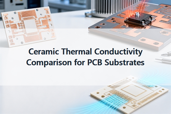
Ceramic thermal conductivity for PCB substrates spans a wide range: common alumina is typically about 24-30 W/m.K, silicon nitride about 70-110 W/m.K, and aluminum nitride about 140-180 W/m.K at room temperature. These values help screen materials, but they do not predict device temperature by themselves. Substrate thickness, heat-source area, copper spreading, metallization, attach layers, thermal interfaces, and the cooling boundary must be evaluated as one heat path.
What Does Ceramic Thermal Conductivity Mean for a PCB?
Thermal conductivity, expressed in watts per meter-kelvin (W/m.K), describes how readily heat moves through a material. When thickness and heat-transfer area are unchanged, a higher value means less resistance through the ceramic layer.
A ceramic PCB uses this property together with electrical insulation. The ceramic can separate a powered conductor from a baseplate or heat sink while still moving heat away from LEDs, laser diodes, RF devices, IGBTs, MOSFETs, or other concentrated sources. This combination is the practical advantage; a conductive metal alone cannot provide the same electrical isolation.
Typical Thermal Conductivity of PCB Ceramic Materials
Use representative values to compare material families, then verify the exact substrate grade and test temperature before releasing a design.
| Material | Representative room-temperature thermal conductivity | PCB selection logic |
|---|---|---|
| Alumina (Al2O3) | About 24-30 W/m.K for common electronic grades | Cost-controlled ceramic circuits with moderate heat flux |
| Aluminum nitride (AlN) | About 140-180 W/m.K for common substrate grades | Compact high-power designs where the ceramic is a thermal bottleneck |
| Silicon nitride (Si3N4) | About 70-110 W/m.K for substrate grades | Power cycling and mechanical reliability where toughness matters |
| Zirconia (ZrO2) | About 2-3 W/m.K | Mechanical or insulation uses that do not require high heat flow |
| FR4 reference | About 0.3-0.5 W/m.K through thickness | Low-cost circuitry without concentrated heat flux |
The range within each family is important. Density, additives, grain structure, porosity, purity, and measurement method can shift the result, so a material name is not an acceptance specification.
Why Do Published Ceramic Thermal Conductivity Values Differ?
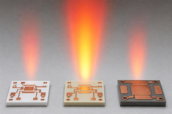
Two datasheets can list different values for nominally similar ceramics because the actual compositions and test conditions are different. Sintering aids and glassy phases can reduce heat flow. Residual pores scatter the phonons that carry heat through the crystal. Grain size, orientation, density, and impurity level also matter.
Temperature is another source of variation. Thermal conductivity for alumina, AlN, and Si3N4 generally declines as temperature rises, so a room-temperature value should not be copied unchanged into a high-temperature model. When temperature margin is tight, request a conductivity-versus-temperature curve or at least a value near the highest steady-state substrate temperature.
For purchasing, specify the approved grade, the minimum required conductivity, and the temperature at which that minimum applies. Purity alone, such as “96% alumina,” is not enough to control the thermal result.
How to Convert Conductivity into Ceramic-Layer Thermal Resistance?
A first-pass through-thickness estimate uses R = t / (k x A), where R is thermal resistance, t is ceramic thickness, k is thermal conductivity, and A is the effective heat-transfer area. This equation shows why conductivity cannot be judged separately from geometry.
For the same area, reducing a 1.0 mm ceramic to 0.5 mm halves its ideal one-dimensional resistance. Changing from 25 W/m.K alumina to 170 W/m.K AlN reduces the ceramic term by roughly a factor of 6.8. The real improvement may be smaller because heat spreads in three dimensions and other layers remain in series.
Use the equation as a screening tool, then model or test the complete assembly when the heat source is small, power density is high, or temperature uniformity is critical.
How Does the Complete PCB Heat Path Change the Result?
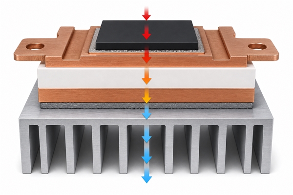
The measured device temperature is set by every layer between the junction and the coolant or ambient environment. A high-conductivity substrate cannot compensate for a voided solder layer, a thick low-conductivity adhesive, poor contact to the heat sink, or inadequate convection.
- Die or package attach: bond-line thickness, voiding, and material conductivity control the first interface.
- Copper or conductor layer: thickness and layout spread heat laterally before it enters the ceramic.
- Ceramic substrate: material grade, thickness, area, and temperature determine its contribution.
- Backside interface: solder, braze, adhesive, or TIM can dominate if it is thick or poorly wetted.
- Baseplate and heat sink: flatness, mounting pressure, airflow, liquid flow, and ambient temperature set the final boundary.
Alumina vs AlN vs Si3N4: Which Substrate Should You Choose?
Choose the material that removes the actual design bottleneck. The highest W/m.K is not automatically the most reliable or cost-effective option.
| Decision factor | Alumina | AlN | Si3N4 |
|---|---|---|---|
| Heat-flow capability | Moderate | Highest among the three | Between alumina and AlN |
| Mechanical toughness | Moderate and brittle | Moderate and brittle | Highest; useful for cycling and vibration |
| Cost position | Usually lowest | Higher | Higher |
| Typical reason to select | Thermal need exceeds FR4, but heat flux remains manageable | Ceramic resistance limits junction temperature or package density | Power cycling, copper stress, and fracture resistance drive reliability |
| Common mistake | Using it after the thermal margin is already exhausted | Paying for conductivity when an interface is the real bottleneck | Selecting it for strength without checking the available conductivity grade |
Alumina is the sensible default when it meets the thermal target. Move to AlN when a thermal model shows that reducing ceramic resistance creates meaningful junction-temperature margin. Consider Si3N4 when repeated thermal cycling or mechanical loading makes substrate fracture a larger risk than achieving the maximum conductivity.
How Do DPC, DBC, and AMB Affect Thermal Performance?
Metallization changes how heat spreads across the substrate and how stress is transferred into the ceramic.
| Construction | Thermal and mechanical effect | Common fit |
|---|---|---|
| DPC | Fine plated copper features support compact routing and localized heat spreading | LEDs, lasers, sensors, optoelectronics, and precision circuits |
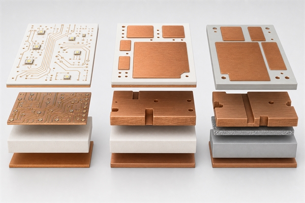
| DBC/DCB | Thick directly bonded copper provides strong lateral spreading and current capacity; copper balance and edge stress need review | Power modules, IGBT, MOSFET, rectifier, and inverter circuits |
| AMB | Active-metal braze bonds copper to ceramics such as Si3N4; the structure is suited to demanding thermal-cycle reliability | Automotive traction, renewable-energy, and industrial power modules |
A single-sided alumina DPC substrate for LED devices is relevant when fine circuitry and moderate heat flow share a compact board. When conductivity is the limiting requirement, an AlN DPC ceramic substrate for high-heat-flux circuits shortens the thermal path through a much more conductive ceramic. For power cycling and high-current modules, a double-sided AMB ceramic substrate for IGBT modules combines thick copper with a mechanically robust ceramic system.
When Is High Ceramic Thermal Conductivity Unnecessary?
Higher conductivity is unnecessary when the ceramic contributes only a small share of total thermal resistance or when the device operates comfortably below its temperature limit with alumina. In that case, AlN may increase substrate, machining, and metallization cost without materially changing the assembly temperature.
Before upgrading the ceramic, check whether the larger improvement comes from a thinner substrate, wider copper heat spreader, larger attach area, lower-void solder process, thinner TIM, flatter interface, larger heat sink, or stronger airflow. If one of these terms dominates, changing the ceramic alone has limited value.
Beryllium oxide can provide high conductivity and electrical insulation, but dust generated during machining requires strict controls. It should not be treated as a routine substitute unless the supply chain, fabrication controls, and compliance requirements are already qualified.
What Should a Ceramic PCB Thermal Specification Include?
A useful drawing and quotation package should control the material and the test condition rather than requesting only a “high-conductivity ceramic PCB.” Include:
- ceramic material family, approved grade, and minimum thermal conductivity;
- conductivity test temperature or required conductivity-versus-temperature data;
- substrate length, width, thickness, thickness tolerance, flatness, and warpage;
- DPC, DBC/DCB, AMB, thick-film, or thin-film construction;
- copper thickness, copper balance, circuit pattern, minimum line/space, and edge clearance;
- surface finish and soldering, die-attach, or wire-bonding requirements;
- device power, heat-source footprint, duty cycle, ambient range, and cooling boundary;
- thermal simulation assumptions, target junction or case temperature, and prototype test points;
- dielectric, adhesion, thermal-cycle, power-cycle, and traceability requirements;
- prototype and production quantities.
BSTCeramicPCB can use these inputs to compare the substrate grade, thickness, copper structure, and interfaces before prototype release. If the thermal boundary conditions are missing, a conductivity value alone cannot confirm whether the assembly will meet its temperature target.
How Should You Validate a Ceramic PCB Prototype?
Start by confirming the incoming substrate grade and controlled properties against the purchase specification. Inspect substrate thickness, flatness, copper thickness, surface finish, metallization adhesion, and visible defects before assembly.
Thermal validation should reproduce worst-case power, ambient temperature, airflow or coolant conditions, mounting pressure, and interface material. Measure at defined locations and compare the result with the model using the same boundary conditions. For power modules, combine steady-state thermal testing with thermal cycling or power cycling when copper stress and ceramic fatigue are reliability concerns.
If the prototype runs hotter than predicted, inspect interface voids, bond-line thickness, contact pressure, heat-sink flatness, copper spreading, and sensor placement before concluding that the ceramic material is out of specification.
FAQ
Which ceramic has the highest thermal conductivity for PCB substrates?
Among widely used PCB substrate ceramics, AlN normally provides the highest conductivity. Common substrate grades are often around 140-180 W/m.K, while premium grades may be higher. Verify the exact grade and test temperature.
What is the thermal conductivity of alumina ceramic?
Common electronic-grade alumina substrates are typically about 24-30 W/m.K at room temperature. Lower-purity or porous grades can be lower, and the approved datasheet should control the design value.
What is AlN ceramic thermal conductivity?
Common AlN substrate grades are often about 140-180 W/m.K at room temperature. The exact value depends on grade, density, impurities, processing, and test method.
Is silicon nitride more thermally conductive than alumina?
Yes, PCB-grade Si3N4 is normally more conductive than alumina and also offers higher fracture toughness. It is selected when power cycling and mechanical reliability justify its higher cost.
Does a thinner ceramic PCB conduct heat better?
Thickness does not change the material's conductivity, but it reduces through-thickness thermal resistance. A thinner substrate creates a shorter heat path when material grade and effective area remain unchanged.
Does ceramic thermal conductivity decrease with temperature?
For common dense substrate ceramics such as alumina, AlN, and Si3N4, conductivity generally decreases as temperature rises. Use temperature-dependent data for elevated-temperature operation.
Is thermal conductivity the same as heat capacity?
No. Thermal conductivity describes the rate of heat flow through a material. Heat capacity describes how much energy the material stores for a given temperature change.
Can a high-conductivity ceramic eliminate a heat sink?
Usually not. The ceramic moves heat toward the cooling structure but does not remove that heat from the system. The baseplate, heat sink, airflow, liquid cooling, and ambient boundary still determine the final temperature.
Conclusion
Ceramic thermal conductivity is a useful first filter, but substrate selection should be based on total thermal resistance and reliability. Alumina is usually the cost-controlled choice, AlN is preferred when ceramic resistance limits heat flow, and Si3N4 is valuable when toughness and power cycling dominate. Control the material grade, temperature condition, thickness, copper structure, interfaces, and cooling boundary before approving production.
For a ceramic PCB material comparison or prototype review, contact BSTCeramicPCB at sales@bstceramicpcb.com with the drawing, heat-source data, operating temperature, cooling conditions, and test requirements.
 Products
 About us
 Contact us



