






















































 HOME


-

Ceramic PCB for Humanoid Robot joint actuators
2026 04,07 -
LTCC PCB Surprises: What Most People Miss
2025 12,09 -
Step-by-Step Guide to DPC PCB Design for Sensor Systems
2025 12,03 -
Ceramic PCBs Essential Benefits and Applications
2025 12,01 -
How Al2O3 DPC Ceramic Substrate PCB Enhances Heat Dissipation in Modern Electronics?
2025 11,28 -
How to Choose Between Ceramic, FR4, and Metal Core PCBs
2025 11,27 -
DPC Ceramic PCB Materials: Surprising Science Inside
2025 11,26 -
Wire bondable 2-layer Alumina substrates PCB | Bstceramic PCB
2025 09,22 -
Silicon Nitride Substrate, Silicon Nitride Ceramic Substrate Formula
2025 05,08 -
What is thick film ceramic PCB?
2023 08,02
When Is a DBC Substrate for EV Inverter the Right Power-Module Choice?
Published:
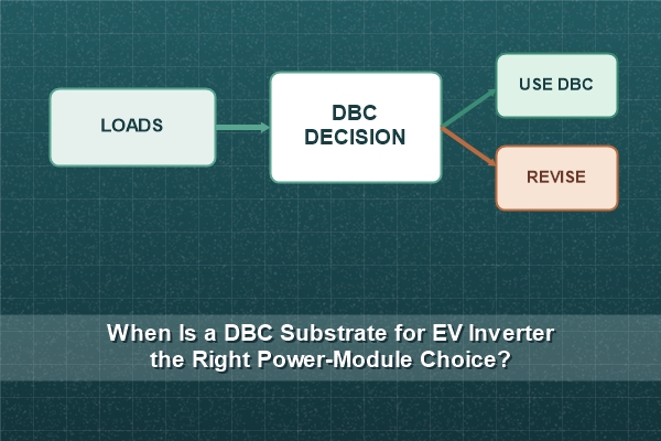
A DBC substrate for EV inverter is the right choice when a direct-bonded copper construction can meet the module's current, thermal, insulation, geometry and cycling requirements with acceptable manufacturing margin. The decision should end with a documented yes or no. It should not begin and end with “DBC is widely used in power electronics.”
What Decision Is DBC Supposed to Solve?
DBC provides a thick copper conductor bonded directly to an alumina or aluminum nitride ceramic. In an EV inverter module, that construction can combine current carrying, electrical isolation and heat transfer in one patterned circuit.
The selection question is whether this construction has enough margin for the actual die map, cooler, voltage, cycling profile and assembly process. If the answer depends on unknown inputs, the project is not ready to select DBC or reject it.
Gate 1: Does the Current Path Need Thick Bonded Copper?
Map phase output, DC link and switching current paths before choosing copper thickness. Use continuous and transient current, conductor length, allowed temperature rise and terminal geometry. A thicker copper layer may reduce resistance, but it also changes etching capability and thermo-mechanical stress.
Our DBC ceramic substrate for IGBT semiconductors is a direct product reference for thick-copper power-semiconductor circuits. The released copper value must be a finished requirement that matches the electrical and manufacturing calculations.
Gate 2: Can the Complete Thermal Stack Meet the Junction Target?
Calculate heat flow through die attach, copper, ceramic, lower copper, substrate attach and cooler. Compare alumina and AlN only after interface resistance and spreading are included. If the ceramic contributes little to the total, a higher-conductivity grade may not justify its cost. If it controls the result, the material and thickness are decisive.
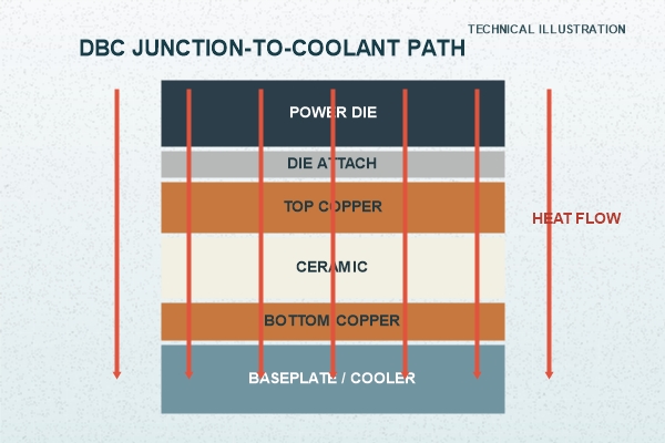
Use the same heat-source footprint, boundary conditions and contact assumptions for each option. Otherwise, the comparison ranks different models rather than different substrates.
Gate 3: Should the DBC Use Alumina or AlN?
Alumina DBC is often sufficient when moderate ceramic heat transfer meets the thermal target and cost control is important. AlN DBC becomes more attractive when the ceramic layer materially limits junction temperature or the design needs a closer thermal-expansion match to the semiconductor stack.
The material choice still requires grade-specific data. Thermal conductivity, strength, dielectric behavior and dimensional capability depend on the supplied ceramic and test conditions. Do not convert a typical datasheet value into a guaranteed finished-board specification without agreement.
Gate 4: Does the Cycling Margin Support DBC or Point to AMB?
DBC can be the correct route when the selected ceramic, copper geometry and module constraint pass the required thermal or power cycling. AMB with Si3N4 deserves evaluation when mechanical toughness and severe cycling margin dominate the decision.
This is not a simple “automotive equals AMB” rule. Our automotive DBC ceramic circuit is a valid route when the application evidence supports it. The test profile and failure analysis should decide whether DBC has adequate margin.
What Does the DBC Selection Matrix Look Like?
Use a decision matrix that produces an action rather than a list of material features.
| Observed project condition | DBC decision | Next action |
|---|---|---|
| Alumina DBC meets thermal and cycling targets | Strong candidate | Freeze geometry and validate the assembly stack |
| Ceramic thermal resistance is the main bottleneck | Keep DBC, evaluate AlN | Recalculate with grade-specific AlN data |
| Required copper geometry exceeds practical etching margin | DBC design needs revision | Change layout, thickness or manufacturing route |
| Cycling failure initiates at copper/ceramic stress zones | DBC margin is uncertain | Optimize geometry and compare Si3N4 AMB |
| Finish or attach route is incompatible | Construction is not release-ready | Select compatible finish and repeat assembly review |
| Insulation method or criterion is undefined | No route can be approved | Define proof test and module insulation plan |
DBC is “right” only after the required rows close with evidence.
What Copper Pattern Rules Keep DBC Manufacturable?
Thick copper etches laterally as well as vertically, so minimum gap, land width and finished dimensions must be checked against copper thickness. Large imbalanced copper areas, sharp internal corners and abrupt neck-downs can also concentrate stress.
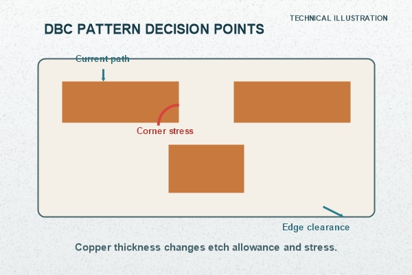
Provide the current direction, die and terminal positions, bond areas, high-voltage spacing and copper-to-edge requirement. We can review manufacturing compensation and corner treatment while preserving the electrical intent of the released design.
Which Surface Finish and Joining Process Must Be Matched?
Choose the finish from the actual die-attach, wire-bond, ribbon, clip and substrate-to-baseplate processes. Nickel plating and ENIG are available DCB finish routes in our capability list, but the project must define the finish thickness, surface condition, storage and acceptance criteria that its joining process needs.
For an automotive plated option, our Ni/Pd/Au DBC ceramic substrate is a relevant product route. It is not automatically interchangeable with bare copper, nickel or ENIG in a qualified assembly.
Which Results Confirm That DBC Is the Right Choice?
The prototype package should show that the artwork and dimensions meet the drawing, the finish supports the joining process, the defined isolation test passes, the complete thermal stack reaches the target and the assembled module survives its required cycling profile.
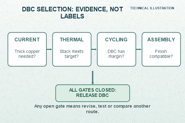
Failure analysis must identify whether a problem came from the DBC circuit, die attach, lower attach, cooler constraint or test fixture. Without that separation, changing the ceramic route can hide rather than solve the root cause.
What Conditions Should Disqualify the Current DBC Design?
Do not release the design when the thermal model still depends on unknown interface values, the required geometry is below the manufacturing limit, copper balance produces uncontrolled distortion, the insulation criterion is undefined, or qualification failures remain unexplained. These conditions do not always disqualify DBC technology; they disqualify the current specification.
The correct action may be a new copper layout, another DBC ceramic, a revised assembly constraint or an AMB comparison. Record the decision and the evidence that closed it.
How Do We Release a DBC Prototype into Production?
We review ceramic callout, finished copper thickness, artwork, finish, dimensions, datums and inspection plan as one controlled package. Our current DCB capability list includes up to two layers, a listed minimum board thickness of 0.30 mm and listed minimum line/space of 0.30/0.30 mm; exact feasibility depends on the actual copper thickness and geometry.
The production baseline should contain approved data, critical characteristics, measurement methods and change-control rules. Prototype concessions must be closed or transferred into the formal documentation before repeat orders.
What Manufacturing Package Should You Send?
For our DBC manufacturability review, send Gerber or ODB++ files, a dimensioned drawing, alumina or AlN preference, finished copper and ceramic thicknesses, current paths, voltage and isolation requirements, die map, finish, joining methods, functional flatness area, cycling target, prototype quantity and forecast volume.
Email the package to sales@bstceramicpcb.com. We will review manufacturability and identify the decision gates that remain open before quotation. A DBC substrate for EV inverter is the right choice only when the evidence closes the electrical, thermal, mechanical and manufacturing requirements together.
 Products
 About us
 Contact us



