






















































 HOME


-

Ceramic PCB for Humanoid Robot joint actuators
2026 04,07 -
LTCC PCB Surprises: What Most People Miss
2025 12,09 -
Step-by-Step Guide to DPC PCB Design for Sensor Systems
2025 12,03 -
Ceramic PCBs Essential Benefits and Applications
2025 12,01 -
How Al2O3 DPC Ceramic Substrate PCB Enhances Heat Dissipation in Modern Electronics?
2025 11,28 -
How to Choose Between Ceramic, FR4, and Metal Core PCBs
2025 11,27 -
DPC Ceramic PCB Materials: Surprising Science Inside
2025 11,26 -
Wire bondable 2-layer Alumina substrates PCB | Bstceramic PCB
2025 09,22 -
Silicon Nitride Substrate, Silicon Nitride Ceramic Substrate Formula
2025 05,08 -
What is thick film ceramic PCB?
2023 08,02
What Is Temperature Coefficient of Resistance?
Published:
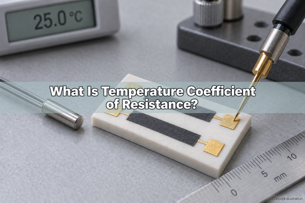
The temperature coefficient of resistance (TCR) describes how much a resistor's value changes per degree of temperature change, relative to its value at a stated reference temperature. It helps you predict whether a circuit that is accurate at room temperature will remain accurate when it heats up. In ceramic circuits, TCR belongs to the resistive element or film, not to the ceramic substrate's thermal conductivity.
What Does Temperature Coefficient of Resistance Mean?
TCR is a fractional change, not a fixed number of ohms per degree. Two resistors with the same TCR can change by different amounts in ohms because their starting resistance values differ. A 100 kohm resistor changes ten times as many ohms as a 10 kohm resistor under the same temperature change and coefficient.
The temperature coefficient of resistance symbol is usually alpha, written as the Greek letter alpha in equations. Datasheets may instead use TCR or TC. Always identify the reference resistance, reference temperature, and specified temperature interval before comparing two values.
What Is the Unit of TCR?
The SI unit of temperature coefficient of resistance is K^-1. Resistor specifications commonly use ppm/deg C or ppm/K. A temperature rise of 1 deg C equals a rise of 1 K, so these two ppm-based units have the same numerical value.
- 1 ppm/deg C = 0.000001 per deg C.
- 25 ppm/deg C = 0.0025% per deg C.
- 100 ppm/deg C = 0.01% per deg C.
A specification of +/-25 ppm/deg C is a limit, not a promise that every resistor has a positive slope of exactly 25 ppm/deg C. The actual slope may be positive, negative, or smaller in magnitude within the stated test conditions.
Temperature Coefficient of Resistance Formula
For two stabilized resistance measurements, the average temperature coefficient of resistance formula is:
TCR (ppm/deg C) = [(R2 - R1) / (R1 x (T2 - T1))] x 1,000,000
Here, R1 is the resistance at reference temperature T1, and R2 is the resistance at T2. Use the same resistance units for both readings. T2 must differ from T1. The result is an average over that interval, referenced to R1; it is not automatically the local slope at every temperature.
For T2 above T1, a positive difference between R2 and R1 gives a positive TCR. A negative difference gives a negative TCR. Retain that sign when using the result to predict resistance.
How Do You Calculate Resistance Change with Temperature?
When a linear approximation is valid, use:
R(T) = Rref x [1 + alpha x (T - Tref)]
Convert alpha from ppm/deg C to per deg C by dividing by 1,000,000. For a 10 kohm resistor with an actual +25 ppm/deg C coefficient, heating from 25 to 85 deg C gives a 60 deg C rise, a 0.15% resistance increase, and a final resistance of 10,015 ohms.
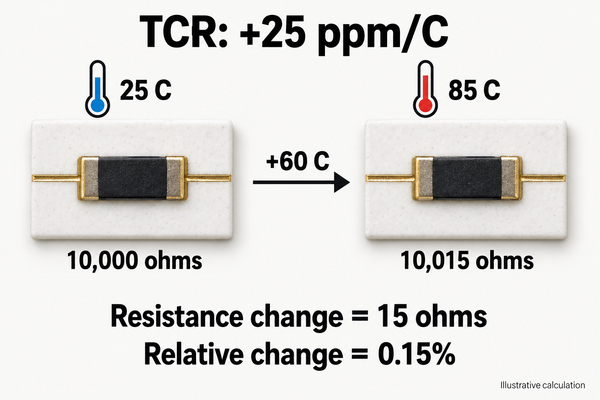
If the datasheet gives a +/-25 ppm/deg C limit, use the corresponding +/-0.15% as a temperature-error allowance over that interval, subject to the datasheet's definition. Keep initial tolerance, aging, and measurement uncertainty separate; this calculation includes none of them.
Positive vs Negative Temperature Coefficient of Resistance
A positive temperature coefficient of resistance means resistance increases as temperature rises. Ordinary metallic conductors generally show this behavior around room temperature because increased lattice vibration scatters charge carriers more strongly.
A negative temperature coefficient of resistance means resistance decreases as temperature rises. NTC thermistors are designed to use this behavior for temperature sensing or other functions. Their resistance-temperature curve is strongly nonlinear, so a single room-temperature TCR should not replace the specified curve or thermistor model.
Semiconductors do not all have one universal coefficient: carrier concentration, doping, material, and temperature range matter. For a precision resistor, a small absolute TCR is usually desirable. For a temperature sensor, a predictable larger response can be useful.
Temperature Coefficient of Resistance Table
Use bulk-material values to understand scale, not to qualify a finished resistor or deposited film. The values below are approximate near room temperature and are not manufacturing acceptance limits.
| Material or element | Approximate coefficient | Practical boundary |
|---|---|---|
| Copper | +0.00393 per deg C, about +3,930 ppm/deg C near 20 deg C | Copper leads and traces can affect low-resistance measurements. |
| Gold | About +0.0034 per deg C, or +3,400 ppm/deg C | A bulk gold value does not specify a plated multilayer circuit's total resistance drift. |
| Silver | About +0.0038 per deg C, or +3,800 ppm/deg C | Do not apply the bulk-metal number directly to a fired silver-containing paste. |
| Platinum | About +0.00392 per deg C near room temperature | RTD grades use defined calibration curves; their specified coefficient may use a different reference interval. |
| Engineered resistor film or alloy | Use the selected grade's specification | Composition, processing, resistance range, and test interval determine the usable value. |
The temperature coefficient of resistance of copper is much higher than the tens-of-ppm limits used in many precision resistors. For a low-ohm element, a small series resistance from copper connections can therefore matter even when the resistor itself has low TCR.
Is Temperature Coefficient of Resistance Constant?
Not necessarily. A constant alpha is a useful approximation over a defined temperature range. If the resistance-temperature curve bends, a two-point average can hide changes inside that interval. Use additional temperature points when intermediate-temperature accuracy matters.
The reference temperature also matters. Even for a perfectly straight resistance-temperature curve, changing the reference resistance changes the numerical fractional coefficient. Do not combine an alpha referenced to 20 deg C with a resistance referenced to 0 deg C without converting the model consistently.
TCR vs Resistor Tolerance
Tolerance describes the starting value; TCR describes its temperature dependence. Choose both from the circuit's error budget rather than assuming a tight tolerance guarantees thermal stability.
| Specification | What it controls | What it does not establish |
|---|---|---|
| Initial resistance tolerance | Deviation from nominal at the specified reference conditions | Resistance over the full temperature range |
| TCR | Reversible resistance change with temperature under defined conditions | Long-term aging or overload damage |
| Load-life stability | Resistance change after a specified powered test | The instantaneous resistance at every operating temperature |
| TCR tracking | Difference in temperature behavior between elements | Identical element temperatures or zero initial ratio error |
Laser trimming sets the initial resistance or ratio. It does not by itself prove that the resistive material has a low TCR. A room-temperature trim result and a temperature sweep answer different acceptance questions.
Thin Film vs Thick Film Resistor TCR
Choose a resistor technology using its guaranteed temperature behavior, power requirements, and circuit function. Thin film is often selected for precision and matching; thick film can be appropriate when its qualified paste and process meet the required drift limit.
| Ceramic circuit approach | TCR-related selection point | Manufacturing information to retain |
|---|---|---|
| Thin-film resistor | Check absolute TCR, tracking, and the specified resistance range | Resistive film system, heat treatment, geometry, trim state, and temperature interval |
| Thick-film resistor | Check the particular paste grade and fired result, not a generic thick-film value | Paste sheet-resistance grade, substrate, firing profile, conductor compatibility, and trim state |
We integrate printed resistors into our thick-film alumina circuits. The electrical requirement must describe the finished resistor after its relevant firing, trimming, and assembly steps, rather than only a paste's nominal room-temperature resistance.
For our thin-film ceramic circuits, laser-trimmable resistance accuracy and TCR are separate specifications. We can review them together, but a special initial-accuracy target must not be treated as an automatic temperature-drift guarantee.
How Does Self-Heating Affect Resistance?
The resistive element can be hotter than the surrounding air because it dissipates power. Use element temperature, or a validated estimate of it, when applying the temperature coefficient of resistance. Ambient temperature alone can underestimate drift.
As an illustrative steady-state estimate, 0.1 W through a thermal path of 100 K/W produces a 10 K rise. At 25 ppm/K, that adds 250 ppm, or 0.025%, of resistance change. The assumed thermal resistance belongs to this example only; mounting, copper area, substrate, airflow, and nearby heat sources change the real value.
An alumina or AlN substrate can affect heat spreading and the temperature reached by the resistor. It does not turn the resistor film's TCR into the substrate's thermal conductivity or coefficient of thermal expansion. Verify thermal performance and electrical drift separately.
Why Does TCR Tracking Matter in Resistor Networks?
For a gain-setting ratio R2/R1, the first-order fractional ratio change is approximately (alpha2 - alpha1) x delta T when both resistors experience the same temperature change. Two resistors with individually low TCR do not necessarily track closely.
For example, coefficients of +25 and -25 ppm/deg C differ by 50 ppm/deg C. Across 60 deg C, their ratio changes by approximately 0.3%. A pair that tracks within 2 ppm/deg C would contribute about 0.012% under the same common temperature change, before initial ratio error and other effects.
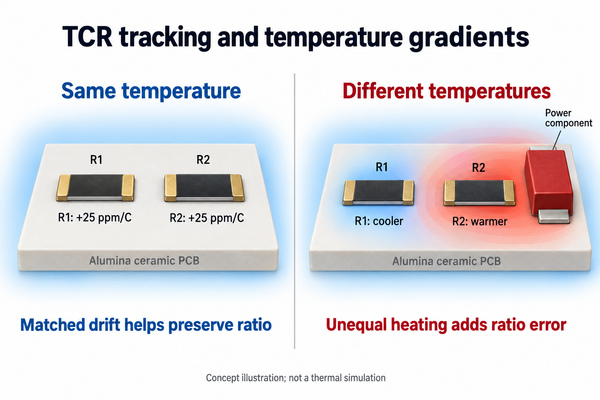
For precision signal paths on medical thin-film ceramic circuits, specify ratio tolerance and tracking if the function depends on a resistor ratio. Also control layout and dissipation: excellent tracking measured at a common temperature cannot cancel a thermal gradient between the two elements.
How Do You Measure TCR on a Ceramic Circuit?
Measure the finished resistor in a controlled temperature setup with low enough electrical power to avoid significant self-heating. A four-wire Kelvin connection is useful when lead or contact resistance would otherwise affect the result.
- Record the reference temperature, actual resistance, connection method, and measurement current.
- Stabilize the circuit at each specified test temperature. Confirm the sample has settled, not just the chamber display.
- Measure resistance with the same electrical conditions and calculate the interval TCR.
- Add intermediate points when curvature matters. Check relevant resistor pairs for ratio drift as well as individual resistance.
- Return to the reference temperature and remeasure. A persistent shift indicates hysteresis, stress, aging, or measurement problems rather than reversible TCR alone.
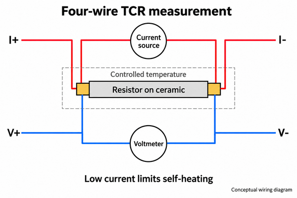
Specify whether acceptance applies before or after trimming, soldering, bonding, or protective coating. Otherwise, prototype measurements and production acceptance can describe different process states even when both reports say "TCR."
How Low Should the TCR Be?
Start with the allowable temperature-related error, not the smallest available ppm number. For an approximately linear response, the maximum permissible magnitude is:
TCR limit (ppm/deg C) = allowable fractional resistance change x 1,000,000 / maximum temperature departure from reference
If temperature drift may consume 0.1% across a maximum 80 deg C departure, the calculated limit is 12.5 ppm/deg C. A 10 ppm/deg C grade may fit that allocation; a 25 ppm/deg C grade does not. Reserve separate allowances for initial tolerance, aging, self-heating uncertainty, and other circuit errors. Use a tracking requirement instead when the critical variable is a resistor ratio.
At BSTCeramicPCB, we can review ceramic circuit drawings with the resistance values, reference temperature, operating range, power dissipation, and absolute or tracking TCR targets. Send these inputs and the required quantity to sales@bstceramicpcb.com so we can assess the process and test requirements. A useful temperature coefficient of resistance specification defines both the allowable change and the conditions under which it must be verified.
 Products
 About us
 Contact us



