






















































 HOME
HOME


-

Ceramic PCB for Humanoid Robot joint actuators
2026 04,07 -
LTCC PCB Surprises: What Most People Miss
2025 12,09 -
Step-by-Step Guide to DPC PCB Design for Sensor Systems
2025 12,03 -
Ceramic PCBs Essential Benefits and Applications
2025 12,01 -
How Al2O3 DPC Ceramic Substrate PCB Enhances Heat Dissipation in Modern Electronics?
2025 11,28 -
How to Choose Between Ceramic, FR4, and Metal Core PCBs
2025 11,27 -
DPC Ceramic PCB Materials: Surprising Science Inside
2025 11,26 -
Wire bondable 2-layer Alumina substrates PCB | Bstceramic PCB
2025 09,22 -
Silicon Nitride Substrate, Silicon Nitride Ceramic Substrate Formula
2025 05,08 -
What is thick film ceramic PCB?
2023 08,02
Aluminium Nitride Dielectric Constant: Values, Frequency and Design Impact
Published:
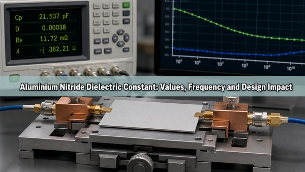
The aluminium nitride dielectric constant is typically about 8.5 to 9.0 for dense commercial AlN measured near room temperature at 1 MHz, although broader supplier specifications may state 8 to 10. This value is not universal. Frequency, temperature, material grade, porosity, sintering additives, electrode geometry, and the test method can all change the reported result. A reliable ceramic PCB model therefore needs a value tied to the actual substrate grade and operating conditions.
What Is the Aluminium Nitride Dielectric Constant?
Dielectric constant, also called relative permittivity or Dk, describes how strongly a material stores electrical energy compared with a vacuum. For an aluminum nitride substrate, Dk affects capacitance, electromagnetic field distribution, signal propagation speed, and the dimensions required for a controlled-impedance conductor.
AlN is electrically insulating even though it conducts heat efficiently. This combination is the reason it is used beneath power semiconductors, LEDs, laser diodes, RF devices, and other components that require both electrical isolation and a short thermal path. Dielectric constant should not be confused with thermal conductivity: the first describes electric-field behavior, while the second describes heat flow.
What Values Are Typical at 1 MHz?
Dense, sintered electronic-grade AlN commonly falls within the ranges below. Values are representative, not acceptance limits. The applicable value must come from the datasheet for the selected grade and should identify temperature, frequency, specimen thickness, and test standard.
| Source or material category | Typical Dk | Stated condition | How to use the value |
|---|---|---|---|
| Dense electronic-grade AlN | About 8.5-9.0 | Room temperature, near 1 MHz | Reasonable starting range for early calculations |
| Kyocera AN2000 example | 8.5 | Typical material value | Use only when the selected grade and test condition are comparable |
| Broad commercial specifications | 8-10 | Often listed at 1 MHz | Screening range, not a substitute for grade-specific data |
| High-frequency characterization | Grade dependent | GHz test fixture and method required | Use measured data for controlled-impedance and RF design |
A single decimal value can imply more precision than the material and test method support. During preliminary layout, use a documented nominal value plus tolerance. Before finalizing a high-frequency circuit, replace that assumption with data for the production substrate.
Why Do Published AlN Dielectric Constant Values Differ?
Published values differ because commercial aluminum nitride is a ceramic system rather than a perfectly pure single crystal. Powder characteristics, oxygen content, sintering aids, grain boundaries, secondary phases, density, and residual porosity alter polarization within the material. Two substrates sold as AlN can therefore have similar thermal conductivity yet slightly different dielectric behavior.
Test configuration creates another source of variation. A parallel-plate capacitance method measures a bulk specimen between electrodes. Resonant methods characterize the material at microwave frequencies. Surface roughness, electrode area, air gaps, edge fringing, sample thickness, fixture calibration, and moisture conditioning can all affect the calculated Dk. Published numbers are comparable only when their conditions are comparable.
How Does Frequency Change AlN Permittivity?
Permittivity can decrease modestly as frequency rises because slower polarization mechanisms cannot follow a rapidly alternating electric field. The change may be small over one frequency range and more important over another, depending on composition and measurement method. A 1 MHz datasheet value should therefore not be copied directly into a multi-gigahertz electromagnetic model without validation.
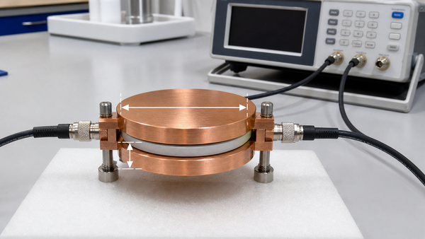
At low frequency, capacitance-based methods are practical. At microwave frequency, split-post dielectric resonators, cavity resonators, or transmission-line test structures are more appropriate. The design model should also distinguish bulk Dk from effective Dk. Effective Dk includes field energy traveling through air, solder mask, adhesive, metallization, and neighboring dielectric layers, so it can differ from the ceramic's bulk value.
How Does Temperature Affect AlN Dielectric Behavior?
Temperature changes lattice polarization and can expose the influence of impurities, defect states, and conductive loss. The direction and magnitude of the change depend on the AlN formulation and test frequency. For a circuit operating across a wide temperature range, room-temperature Dk alone cannot establish impedance stability or capacitance drift.
Temperature-dependent validation should use the actual operating range and a controlled heating profile. The test coupon must reach thermal equilibrium before each measurement. Metal expansion, fixture movement, connector phase change, and temperature-dependent conductor resistance should be separated from the ceramic response. Power modules may also need thermal-cycling checks because cracks, delamination, or void growth can change the effective electrical structure even when the intrinsic AlN permittivity remains stable.
How Do Purity, Oxygen, Porosity, and Sintering Additives Affect Results?
AlN powder readily reacts with oxygen at particle surfaces. During densification, oxygen and sintering aids can form secondary phases at grain boundaries. These phases help achieve a dense body but may change both dielectric loss and permittivity. The final result depends on additive chemistry, firing atmosphere, peak temperature, dwell time, cooling cycle, and post-firing treatment.
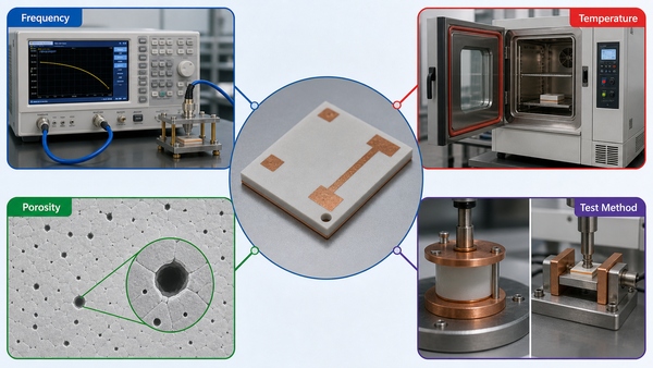
- Higher density: reduces air-filled porosity and generally produces a more consistent bulk dielectric response.
- Residual pores: lower effective permittivity because air has a Dk close to 1, while also reducing thermal conductivity and mechanical strength.
- Oxygen and secondary phases: can alter dielectric loss, insulation resistance, and the frequency response.
- Grain structure: affects how uniformly electric and thermal fields pass through the ceramic.
- Surface preparation: influences electrode contact and thin-film behavior even when the bulk composition is unchanged.
Purity percentage alone is therefore an incomplete specification. Density, thermal conductivity, loss tangent, volume resistivity, surface roughness, and lot consistency provide a more useful description of an electronic substrate.
How Is AlN Dielectric Constant Measured?
For a parallel-plate method, conductive electrodes of known area are applied to opposite faces of a flat AlN specimen. An LCR meter measures capacitance at a specified frequency and voltage. Relative permittivity is then calculated from capacitance, electrode area, vacuum permittivity, and specimen thickness. Thickness and electrode dimensions need sufficient accuracy because their measurement errors transfer directly into the result.
The specimen should be clean, dry, flat, and free from edge damage beneath the electrode. Air gaps between deposited or clamped electrodes and the ceramic can lower the apparent value. Guard electrodes may be used to control fringing and leakage. The report should state the standard, fixture, electrode material, frequency, test voltage, temperature, humidity, conditioning, specimen dimensions, and number of samples.
At GHz frequencies, resonator or transmission-line methods are preferred because fixture parasitics dominate ordinary capacitance measurements. These methods should report both permittivity and dielectric loss over the frequency range relevant to the circuit.
What Is the Difference Between Dielectric Constant, Loss Tangent, Strength, and Resistivity?
These properties answer different design questions and cannot replace one another.
| Property | What it describes | Typical unit | Primary design effect |
|---|---|---|---|
| Dielectric constant | Electric energy storage relative to vacuum | Dimensionless | Impedance, capacitance, field distribution, signal speed |
| Loss tangent | Energy dissipated by the dielectric under AC excitation | Dimensionless | Insertion loss and dielectric heating |
| Dielectric strength | Electric field sustained before breakdown under a stated test | kV/mm | Minimum insulation thickness and voltage margin |
| Volume resistivity | Resistance to DC leakage through the material | Ohm-cm | Leakage current and insulation stability |
A material with a suitable dielectric constant can still be unsuitable if loss, leakage, or breakdown strength fails the operating requirement. High-voltage layouts must also account for surface creepage, contamination, metallization edges, voids, and environmental conditions rather than relying only on the bulk dielectric-strength figure.
How Does AlN Compare with Al2O3 and Si3N4?
Dielectric constant is only one part of the material decision. Alumina, AlN, and silicon nitride all provide electrical insulation, but their thermal and mechanical behavior differs substantially.
| Material | Typical Dk near 1 MHz | Thermal characteristic | Mechanical characteristic | Common selection reason |
|---|---|---|---|---|
| AlN | About 8.5-9.0 | High thermal conductivity | Moderate fracture toughness | High heat flux with electrical isolation |
| Al2O3 | Often about 9-10, grade dependent | Moderate thermal conductivity | Established and stable | General ceramic circuits and cost balance |
| Si3N4 | Often below alumina, grade dependent | Good thermal performance | High strength and fracture toughness | Power modules under severe thermal cycling |
For a detailed alumina reference, see the article on Al2O3 dielectric constant. Silicon nitride designs should use grade-specific data such as those discussed in silicon nitride dielectric constant and material properties.
How Does Dielectric Constant Affect Impedance and Signal Speed?
A higher effective dielectric constant increases capacitance per unit length and reduces electromagnetic propagation speed. For a given conductor geometry, it also changes characteristic impedance. A controlled-impedance line on AlN therefore cannot reuse FR4 dimensions without recalculation. Conductor width, copper thickness, ceramic thickness, ground spacing, surface finish, and the surrounding air or encapsulant all enter the model.
Bulk Dk is appropriate only when the field is almost entirely confined within the ceramic. Coplanar and microstrip structures place a meaningful part of the field in air or an overcoat, so an electromagnetic solver should use the complete cross-section. At high frequency, conductor roughness, thin-film adhesion layers, plated finishes, and dielectric loss can affect insertion loss as much as the nominal Dk.
How Does It Affect Capacitance and Isolation?
For equal electrode area and dielectric thickness, capacitance rises with dielectric constant. This is useful for integrated capacitors and can also create unwanted parasitic coupling between adjacent conductors, a conductor and a heat spreader, or a device pad and the backside metal. Reducing spacing or substrate thickness increases this coupling.
Electrical isolation is not set by Dk. Isolation depends on ceramic thickness, dielectric strength under the applicable waveform, surface creepage distance, conductor edge geometry, voids, metallization defects, humidity, contamination, and partial-discharge behavior. A design may have stable capacitance yet insufficient voltage margin, so capacitance and insulation checks must remain separate.
When Is an AlN Substrate Better than Alumina?
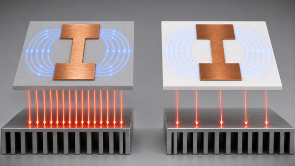
An aluminum nitride substrate is most useful when heat must cross the dielectric directly beneath a compact device and alumina would create excessive temperature rise. Examples include power semiconductor drivers, LED emitters, laser packages, RF power amplifiers, thermoelectric assemblies, and dense sensor modules.
AlN is not automatically required when heat generation is low, copper spreading area is generous, or the dominant thermal resistance lies in solder, interface material, baseplate, or cooling hardware. Alumina may provide sufficient electrical performance with more established processing. Silicon nitride may be preferable when mechanical reliability under repeated thermal cycling is the governing constraint.
What Data Should Be Used in PCB Simulation?
Use a material model that matches the production substrate grade, not a generic internet value. The model should identify nominal Dk and tolerance at the analysis frequency, temperature dependence over the operating range, loss tangent, ceramic thickness and tolerance, copper or film thickness, conductor conductivity, surface roughness, and any solder mask, glass, adhesive, or encapsulant.
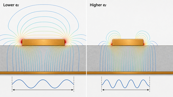
For controlled impedance, model the actual trace cross-section and verify it with a representative coupon fabricated by the same process as the circuit. For insulation analysis, include conductor edge radii, ceramic defects, surface condition, creepage path, transient voltage, and environmental derating. For thermal analysis, enter thermal conductivity separately; dielectric constant has no direct role in steady-state heat conduction.
FAQ About Aluminium Nitride Dielectric Constant
What is the dielectric constant of nitride?
There is no single value for "nitride" because aluminum nitride, silicon nitride, gallium nitride, and other nitrides are different materials. Dense electronic-grade AlN is commonly about 8.5-9.0 near room temperature and 1 MHz, while the exact value depends on grade and test condition.
Is aluminum nitride electrically conductive?
No. Aluminum nitride ceramic is an electrical insulator with high volume resistivity. It is, however, a strong thermal conductor compared with most electrical insulators. Conductive behavior can change if the ceramic is contaminated, damaged, or exposed to conditions outside its material specification.
Is AlN ionic or covalent?
AlN bonding has strong covalent character with a partial ionic contribution. For PCB design, its practical consequences are electrical insulation, useful thermal transport, chemical stability under controlled conditions, and a dielectric response that depends on composition and microstructure.
Can a 1 MHz dielectric constant be used at GHz frequencies?
It can support an early estimate, but it should not be the final model for an RF or microwave circuit. Use high-frequency data for the selected grade and validate the fabricated transmission structure because fixture method, effective Dk, conductor geometry, and surrounding materials become important.
Does higher AlN thermal conductivity mean a lower dielectric constant?
Not necessarily. Thermal conductivity and dielectric constant arise from different physical behavior. Powder purity, oxygen, additives, density, and grain boundaries can affect both, but there is no universal one-to-one conversion between them.
Conclusion
The aluminium nitride dielectric constant is commonly around 8.5-9.0 at room temperature near 1 MHz, with broader commercial ranges of 8-10. The correct design value must match the substrate grade, frequency, temperature, and measurement method. Keep Dk separate from dielectric loss, breakdown strength, volume resistivity, and thermal conductivity, and validate high-frequency or high-voltage behavior with a representative structure.
BSTCeramicPCB supports AlN ceramic circuit development with substrate selection, DPC processing, metallization, dimensional review, and production communication. For a technical discussion about an AlN ceramic PCB, contact sales@bstceramicpcb.com.
 Products
 About us
 Contact us



