


 HOME
HOME

-

DBC Welding Strength Compared to Other Materials
2025 12,19 -
LTCC PCB Surprises: What Most People Miss
2025 12,09 -
Comparison of DBC PCBs and MCPCBs for Cooling Performance
2025 12,03 -
Step-by-Step Guide to DPC PCB Design for Sensor Systems
2025 12,03 -
Ceramic PCBs Essential Benefits and Applications
2025 12,01 -
How Al2O3 DPC Ceramic Substrate PCB Enhances Heat Dissipation in Modern Electronics?
2025 11,28 -
How to Choose Between Ceramic, FR4, and Metal Core PCBs
2025 11,27 -
DPC Ceramic PCB Materials: Surprising Science Inside
2025 11,26 -
Wire bondable 2-layer Alumina substrates PCB | Bstceramic PCB
2025 09,22 -
Silicon Nitride Substrate, Silicon Nitride Ceramic Substrate Formula
2025 05,08 -
How to choose the appropriate substrate for ceramic circuit boards?
2023 11,16 -
Laser Cutting or Water Saw Cutting? How To Choose the Best Cutting Solution for Ceramic Circuit Boards
2023 11,13 -
Why Ceramic PCB Is So Expensive?
2023 11,10 -
Which Process Ceramic Circuit Board Is A Better Solution For Semiconductor Refrigerator Chips?
2023 11,06 -
Silicon Printing Circuit Boards For Advancing Electronics
2023 10,27 -
What is the Difference Between HTCC and LTCC Ceramic PCB
2023 10,06 -
What is the Difference Between 96% and 99% Aluminum Oxide in Ceramic PCBs?
2023 09,20 -
Why thick film ceramic PCB is good for oil level sensor in automotive industry?
2023 08,25 -
Statistical analysis of ceramic PCB application fields
2023 08,16 -
Notice of anti-static requirements for PCBA processing and production
2023 08,16 -
Silver Paste: The Best Conductor Material for Via Holes in Thick Film Ceramic Boards
2023 08,16 -
Testing Circuit Board Ceramic Diode Fuses: A Complete Guide
2023 08,07 -
Why DBC is replaced by DPC in ceramic PCB manufacturing?
2023 08,01 -
What is thick film ceramic PCB?
2023 08,02
Comparing Ceramic and Other PCB Types for High-frequency Applications
You want great results for high-frequency uses, so you should pick a high-frequency ceramic PCB. This board is special because it has a low dielectric constant. That helps keep the signal strong. You also get a low loss tangent, so less energy becomes heat. A ceramic PCB does not let in much water and stays steady when it gets hot or cold. These features make it a smart choice for engineers who want good performance and reliability.
Key Takeaways
- Pick high-frequency ceramic PCBs for better signal quality and reliability. They are very good at keeping signal loss low and staying stable with heat.
- Use PTFE boards if you need very little signal loss. These boards work well in microwave and radar systems.
- FR4 PCBs cost less and work for most electronics, but they may not do well with high-frequency jobs.
- Check how your PCB handles heat. Ceramic PCBs get rid of heat better than FR4, so they are good for high-power uses.
- Always pick a PCB that fits your project. Think about things like frequency range, power needs, and the environment.
Best PCB for High-frequency
Key Differences
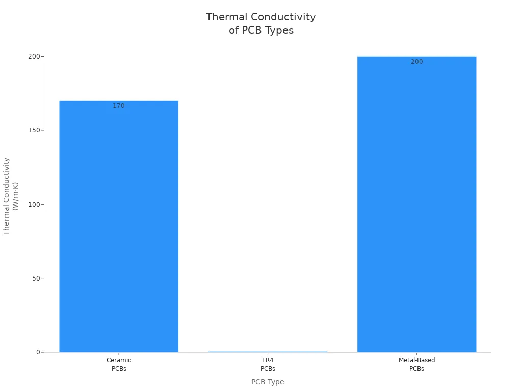
It is important to pick the right board for your project. High-frequency ceramic pcb is special because it gives strong electrical performance and stays stable. When you look at different materials, you notice they act differently with heat, stress, and signals. The table below shows how ceramic pcb, FR4, and metal-based boards are different:
| Feature | Ceramic PCBs | FR4 PCBs | Metal-Based PCBs |
|---|---|---|---|
| Thermal Conductivity | Up to 170 W/m·K (AlN) | 0.3-0.5 W/m·K | ~200 W/m·K (Aluminum) |
| Mechanical Strength | High rigidity, resistant to stress | Lower tensile strength | Good, but less than ceramics |
| Electrical Insulation | Excellent, low dielectric loss | Less effective, potential signal loss | Moderate, struggles in high-frequency environments |
| Cost | Higher due to advanced materials | Lower, widely used | Moderate, cost-effective for medium-power applications |
| Ideal Applications | High-power, high-frequency, aerospace | General-purpose electronics | Medium-power, heat sinking in LEDs |
High-frequency ceramic pcb has great thermal conductivity and electrical insulation. FR4 is good for most electronics, but it loses signal at high frequencies. Metal-based boards are good for heat, but they do not match the electrical performance of ceramic pcb.
Ceramic pcb is also strong and does not bend easily under stress. It costs more, but you get better results for hard jobs.
Suitability Overview
You need to know which board is best for high-frequency needs. High-frequency ceramic pcb is best when you want low signal loss and high reliability. PTFE boards are also good because they have a low dielectric constant and loss tangent. Rogers laminates and ceramic-filled PTFE are strong for signal transmission and mechanical strength.
Here is a table that shows how each material works for high-frequency pcbs:
| Material | Suitability for High-Frequency Applications | Key Properties |
|---|---|---|
| Ceramic | High | Exceptional thermal conductivity, low dielectric losses |
| FR4 | Moderate | Cost-effective, versatile, but lower high-frequency capabilities |
| PTFE | High | Extremely low dielectric constant and loss tangent |
| MCPCBs | Variable | Focused on thermal management, depends on construction and materials used |
PTFE (Polytetrafluoroethylene), also called Teflon, is known for being one of the lowest-loss PCB materials. It has a very low dielectric constant (about 2.1–2.3) and a very low loss tangent. This makes it great for high-frequency and microwave uses.
You can use this list to help you choose:
- Ceramic: Has excellent electrical insulation and stays stable with low dielectric losses.
- FR4: Works well for many frequencies but is not the best for high-frequency.
- PTFE: Has low-loss properties, so it is good for high-frequency and microwave uses.
- MCPCBs: Used mostly for heat control but can work for high-frequency if designed right.
High-frequency ceramic pcb gives the best mix of electrical performance, heat handling, and strength. You should pick ceramic pcb if your project needs top signal quality and reliability. PTFE and Rogers laminates are also good for high-frequency pcbs, but ceramic pcb is best for tough jobs and hard conditions.
Types of High-frequency PCBs
When you use high-frequency pcbs, you should know the main types. Each type has special features for signals, heat, and reliability. Here are the most common choices in electronics.
Ceramic PCBs
Ceramic pcbs are good for tough high-frequency jobs. They use materials like aluminum nitride and silicon carbide. These boards move heat away fast and are very strong. Ceramic pcbs work well even when it gets hotter than 350°C. You can find them in microwave, RF, and high-power projects.
Tip: Ceramic pcbs keep signals clear because they have strong electrical insulation and low dielectric constants.
- Moves heat away fast
- Very strong
- Stays stable in high heat
- Has low dielectric constant
FR4 PCBs
Fr4 is used a lot in high-frequency pcbs. It is popular because it costs less and is easy to use. Fr4 works for frequencies up to 500 MHz or more. High-frequency fr4 has a lower dielectric constant and dissipation factor. This helps keep signals strong and clear.
Note: Fr4 is good for most electronics, but signals may get weaker at very high frequencies.
- Helps keep signals strong
- Makes signals clear
- Used in many designs
- Works for both rigid and flex boards
- Supports fast signals
- Can work up to 100 GHz sometimes
- Used in RF and microwave projects
- Handles heat okay
- Easy to make
- Costs less than ceramic pcbs
PTFE PCBs
PTFE is a good choice for high-frequency pcbs when you want very low dielectric loss. PTFE has a dielectric constant around 2.0–2.2 and a very low dissipation factor. This means signals stay strong and do not lose much energy. PTFE is great for microwave, radar, and fast systems.
| Material | Dielectric Constant | Dissipation Factor | Dielectric Loss at High Frequencies |
|---|---|---|---|
| PTFE | 2.0-2.2 | 0.0005-0.002 | Low |
| Ceramic | Higher | Higher | Greater |
- Keeps signals strong
- Has a stable structure
- Works well for high-frequency pcbs
MCPCBs
MCPCBs are used for high-frequency pcbs when you need to manage heat well. MCPCBs have metal cores, often aluminum, to move heat away from parts. These boards move heat fast and last longer. You can make small circuits with MCPCBs, but they can cost more and be harder to design.
| Advantages | Disadvantages |
|---|---|
| Moves heat fast | Costs more |
| Lasts longer | Harder to design |
| Good for small circuits | Can be heavy |
| Parts last longer | |
| Some are lightweight |
MCPCBs are best when you need to control heat and help parts last longer in high-frequency pcbs.
Pick the right board by thinking about signal quality, heat, and cost. Ceramic pcbs, fr4, PTFE, and MCPCBs each have their own strengths for high-frequency pcbs.
High-frequency Ceramic PCB Properties
Dielectric Constant and Loss
When you pick a PCB for high-frequency work, check the dielectric constant. Ceramic PCBs have a dielectric constant between 3 and 10. This range helps signals stay strong and clear. If the dielectric constant is lower, signals move faster. You get better performance at high frequencies.
- Dielectric constant for ceramic PCBs is 3 to 10
- It helps stop signal loss
- It keeps high-frequency operation steady
Think about dielectric loss too. This shows how much energy turns into heat. Ceramic PCBs have a lower dielectric loss tangent than fr4 and PTFE. Look at the table below to see the difference:
| Material Type | Dielectric Loss Tangent Range |
|---|---|
| Ceramic PCBs | Lower than fr4 and PTFE |
| fr4 | 0.001 - 0.005 |
| PTFE | 0.0001 - 0.002 |
A lower loss tangent keeps signals strong at high speeds. That is why ceramic PCBs are great for high-frequency designs.
Thermal Conductivity
Thermal performance is very important in high-frequency circuits. Ceramic PCBs move heat much better than fr4 or PTFE. Ceramic materials can have thermal conductivity 20 to 100 times higher than fr4. This means heat leaves hot parts quickly. Your system stays safe.
| PCB Type | Thermal Conductivity (W/m·K) |
|---|---|
| fr4 | ~0.3 |
| Ceramic | 20-200 |
Different ceramic materials have different thermal performance:
| Material | Thermal Conductivity (W/m·K) |
|---|---|
| Alumina (Al₂O₃) | ~20-30 |
| Aluminum Nitride (AlN) | ~150-200 |
If you use fr4, heat can build up more. Ceramic PCBs help stop overheating. They make high-frequency projects more reliable.
Mechanical Stability
Mechanical stability helps your board last longer. It also helps it work well in tough places. Ceramic PCBs resist stress much better than fr4. They keep their shape and size, even if the temperature changes fast. This matters for high-frequency circuits. Even small changes can cause problems.
| Aspect | Ceramic PCBs | fr4 PCBs |
|---|---|---|
| Mechanical Stress | Highly resistant to mechanical stress | Can warp or crack under strain |
| Thermal Stability | Maintains dimensions under thermal stress | Prone to dimensional changes |
| Application Suitability | Ideal for rugged environments | Less suitable for extreme conditions |
- Ceramic PCBs have low coefficients of thermal expansion (CTE).
- This lowers thermal stress on solder joints.
- You get better reliability when temperatures change.
- There is less risk of microcracks in parts.
- Important sizes stay stable in precise jobs.
Ceramic PCBs keep their size even when temperatures change. This helps stop problems like solder joint failure. Your high-frequency circuits keep working well.
Ceramic Multilayer PCB and Alternatives
Multilayer Ceramic PCB Features
Ceramic multilayer pcb is good for high-frequency circuits. This board has many ceramic layers stacked together. Each layer helps your circuit work better. It also helps your board last longer. You get lots of benefits from this design. The table below shows the main features and how they help:
| Feature | Benefit |
|---|---|
| Excellent thermal conductivity | Moves heat away fast, keeps parts at safe temperatures. |
| High reliability | Makes circuits work well in tough places, helps them last longer. |
| Superior signal integrity | Keeps signals strong when they move fast, so they stay clear. |
| Low high-frequency loss | Helps signals stay strong in high-frequency jobs. |
| Good thermal expansion coefficient | Stops chips from getting stressed by heat, so parts last longer. |
Ceramic multilayer pcb keeps signals clear and parts cool. This board works well where heat or shaking might cause trouble. You also get better signal quality. That is important for high-frequency jobs.
Comparison with Other Multilayer PCBs
You may wonder how ceramic multilayer pcb compares to fr4 and PTFE boards. Here are some key points to help you choose:
- Ceramics and PTFE keep signals stronger than fr4. You lose less signal at high frequencies.
- Fr4 boards can have many layers. But ceramics and PTFE work better for high-frequency circuits.
- Fr4 costs less. That is why it is used in many electronics. Ceramics and PTFE cost more but work better for hard jobs.
- You can mix fr4 and PTFE layers. This helps you get the right mix of cost and performance.
Tip: Pick ceramics or PTFE for best signals and heat control. Use fr4 if you want to save money and do simple jobs.
Fr4 is in many products because it is cheap and easy to use. If you need better results, ceramics and PTFE help your circuits work faster and last longer.
Electrical Performance Comparison
Signal Integrity
You want your signals to stay strong and clear. Signal integrity means your board keeps signals from getting weak or messy. Ceramic PCBs help with this because they use special materials. These materials have low dielectric constants and low loss tangents. That means signals do not fade or change shape, even at high speeds over 10 GHz.
Here are some key things about signal integrity in ceramic PCBs:
- Dielectric constant (Dk) between 2 and 4 at 10 GHz keeps signals fast.
- Dissipation factor (Df) less than 0.005 means less signal loss.
- Coefficient of thermal expansion (CTE) between 10 and 20 ppm/°C keeps the board steady.
- Thin substrates (10 to 20 mil) are best for very high frequencies.
- Low moisture absorption rate under 0.1% keeps the board working well.
- Low loss tangent means signals do not get weak.
Ceramic PCBs keep signals better than fr4. Fr4 boards can lose signal strength at high speeds. You see more noise and signal problems with fr4, especially above 1 GHz. Ceramic PCBs keep signals clean and steady.
Tip: Pick ceramic PCBs if you want strong and clear signals for high-frequency jobs.
Frequency Response
Frequency response shows how your board handles fast signals. You want your PCB to keep up with quick signals and not lose quality. Ceramic and PTFE PCBs are good for high-frequency uses. They have low dielectric constants and stay stable when hot. This helps your board keep signals strong as speeds go up.
- fr4 can work up to about 1 GHz. After that, signal loss gets worse.
- Ceramic PCBs and PTFE boards work at much higher speeds. They keep signals strong in things like radar and telecom.
- fr4 is not good for very fast jobs. You get more signal loss and weaker results.
Ceramic PCBs give you a steady frequency response. You get less signal loss and better results in hard jobs. PTFE boards also work well, but ceramic PCBs are stronger and handle heat better.
| PCB Type | Max Frequency Range | Signal Loss at High Frequency | Suitability for Advanced Applications |
|---|---|---|---|
| fr4 | Up to ~1 GHz | High | Not recommended |
| Ceramic | 10 GHz and above | Low | Excellent |
| PTFE | 10 GHz and above | Very Low | Excellent |
You should use ceramic PCBs when you need the best high-frequency performance and strong, fast signals.
Physical and Thermal Comparison
Heat Management
High-frequency circuits get hot fast. You need to control heat well. Ceramic PCBs move heat away better than fr4 or PTFE. There are many ways to keep your board cool and safe:
- Ceramics and metal core PCBs have high thermal conductivity. They move heat away from hot spots faster than fr4.
- Put hot parts where air can flow around them. This helps cool the board and keeps fr4 from getting too hot.
- Add thermal vias to your design. These small holes let heat move between layers. This helps both ceramic and fr4 PCBs work better.
- Use thicker copper layers. Thick copper spreads heat better. This helps fr4 boards handle more power.
- Attach heat sinks or thermal pads to hot parts. These tools pull heat away and protect fr4 and ceramic PCBs.
- Use fans or liquid cooling for extra cooling. Fans and liquid keep fr4 and ceramic boards safe, even in hard jobs.
Tip: Always check where you put your parts. Good placement helps fr4 and ceramic PCBs stay cool and last longer.
If you use fr4, you must watch heat closely. Ceramic PCBs work better for high-frequency and high-power jobs. PTFE boards help with heat too, but ceramics are best for top performance.
Durability
You want your PCB to last through many temperature changes. Ceramic PCBs are stronger than fr4 and PTFE boards. The coefficient of thermal expansion (CTE) shows how much a material grows or shrinks when heated. Lower CTE means less stress and fewer cracks.
Here is a table that compares ceramic, fr4, and PTFE PCBs:
| PCB Type | Coefficient of Thermal Expansion (CTE) | Thermal Stability Comparison |
|---|---|---|
| fr4 | 14-17 ppm/°C | More stress when temperatures change |
| Ceramic | 4.5-7.5 ppm/°C | Less stress, works better |
| PTFE | Not specified | Good stability, but not as good as ceramic or fr4 |
Ceramic PCBs do not bend or crack easily. They work well in tough places. fr4 boards can bend or break if temperatures change fast. PTFE boards are stable, but ceramics are best for high-frequency and high-power uses.
Note: If you need your board to survive hard jobs, ceramic PCBs are a smart pick. fr4 works for many uses, but ceramics last longer and handle heat better.
Fabrication and Cost Factors
Manufacturing Complexity
You face many challenges when you make high-frequency ceramic PCBs. These boards need careful design and precise work. You must pay attention to every detail because small mistakes can cause big problems. Here are some main challenges you will see:
- Design complexity and high-density requirements push you to use advanced tools and skills. You need to fit more parts into smaller spaces.
- Material selection and cost control matter a lot. You must choose the right ceramic material for your job and keep costs low.
- High-quality standards and testing requirements make you check every board carefully. You want to avoid defects that can hurt performance or safety.
- Technical challenges in the manufacturing process can slow you down. You must solve problems with assembly and keep everything working well.
You will notice that fr4 boards are much easier to make. You can finish fr4 prototypes in just one day. Ceramic PCBs take longer, sometimes up to two weeks. You need more time and skill for ceramic boards, especially for high-frequency uses.
Cost vs. Performance
You must think about cost when you pick a PCB for high-frequency jobs. Ceramic PCBs cost much more than fr4 boards. PTFE boards also cost more, but they offer great performance. Look at this table to see how prices compare:
| Material | Cost Range (per square inch) |
|---|---|
| fr4 | $0.10 - $0.50 |
| Ceramic | $2.00 - $10.00 |
| PTFE/Rogers | $5.00 - $20.00 |
You pay less for fr4, but you get lower performance at high frequencies. Ceramic PCBs give you better signal quality and heat control, but you spend more money. PTFE boards offer very low signal loss, but they cost even more than ceramic in some cases.
- Ceramic PCBs are much more expensive than fr4 boards. You may pay thousands for ceramic, but only hundreds for fr4.
- Lead times for ceramic PCBs are longer. You wait 10–15 days for ceramic, but only 24 hours for fr4 prototypes.
Tip: If you need top performance and reliability, ceramic PCBs are worth the extra cost. If you want to save money and finish fast, fr4 is a good choice for simple jobs.
You must balance your budget with your need for high-frequency performance. fr4 works well for many projects, but ceramic and PTFE boards help you reach higher speeds and better results.
Applications of Ceramic PCBs

Microwave and RF Uses
Ceramic pcbs are used a lot in microwave and RF systems. These boards help signals stay clear and steady. High-frequency devices need materials that do not lose signal strength. Ceramic pcbs have low signal loss and are very reliable. You can find them in radar, satellite receivers, and wireless base stations. Many engineers pick ceramic pcbs for 5g because they handle fast signals better than fr4. They are also used in RF amplifiers and filters. These boards let you reach higher frequencies without losing signal quality.
Note: Ceramic pcbs keep circuits working well even if the temperature changes fast. This is why they are a great choice for microwave and RF work.
Other High-frequency Applications
Ceramic pcbs are also good for many other high-frequency jobs. You can use them in automotive radar, medical imaging, and aerospace systems. These boards help make sensors that need fast and accurate signals. In power electronics, ceramic pcbs move heat away from parts better than fr4. This helps devices last longer. You might use ceramic pcbs in laser drivers or high-speed digital circuits. When you need strong signal integrity, ceramic pcbs work better than fr4. You can trust them in tough places where fr4 might not work well.
Here is a simple table to show where you might use ceramic pcbs and fr4:
| Application Area | Ceramic PCBs | fr4 |
|---|---|---|
| Microwave/RF | ✅ | ❌ |
| 5G Base Stations | ✅ | ❌ |
| Automotive Radar | ✅ | ❌ |
| Power Electronics | ✅ | ✅ |
| Consumer Electronics | ❌ | ✅ |
Tip: Pick ceramic pcbs when you need high-frequency performance, strong heat control, and boards that last a long time.
Choosing the Right PCB
Decision Criteria
You want your high-frequency project to work well and last a long time. You should start by listing what your application needs. Think about the frequency range, how much power your board will handle, and the environment where you will use it. You also need to check if your board will face mechanical stress or must meet safety rules.
Here is a simple list to help you decide:
- Define what your project needs. Write down the frequency, power, and environment.
- Look at signal integrity. Pick materials with low and stable dielectric constant and loss tangent. Smooth copper foil helps keep signals clear.
- Check thermal management. Choose materials with good thermal conductivity and low coefficient of thermal expansion. This helps your board handle heat.
- Compare performance and cost. High-performance boards like ceramic and PTFE cost more than fr4. Sometimes you can mix materials to save money.
- Make sure you can manufacture the board easily. fr4 is easy to make, but ceramic and PTFE need special tools.
- Think about long-term reliability. Pick materials that do not absorb much water and can handle temperature changes.
- Make sure your board meets safety and industry standards.
Tip: Always balance performance with cost. Sometimes fr4 works well for simple jobs, but you need ceramic or PTFE for tough, high-frequency tasks.
Application-specific Tips
You should match your PCB choice to your project. If you build a microwave or RF device, ceramic boards give you strong signal integrity and heat control. For consumer electronics, fr4 is a smart pick because it costs less and is easy to make. If you need very low signal loss, PTFE boards work well, but they cost more.
Here is a table to help you choose:
| Application Type |
|---|
 Products
 About us
 Contact us