






















































 HOME
HOME


-

Ceramic PCB for Humanoid Robot joint actuators
2026 04,07 -
LTCC PCB Surprises: What Most People Miss
2025 12,09 -
Step-by-Step Guide to DPC PCB Design for Sensor Systems
2025 12,03 -
Ceramic PCBs Essential Benefits and Applications
2025 12,01 -
How Al2O3 DPC Ceramic Substrate PCB Enhances Heat Dissipation in Modern Electronics?
2025 11,28 -
How to Choose Between Ceramic, FR4, and Metal Core PCBs
2025 11,27 -
DPC Ceramic PCB Materials: Surprising Science Inside
2025 11,26 -
Wire bondable 2-layer Alumina substrates PCB | Bstceramic PCB
2025 09,22 -
Silicon Nitride Substrate, Silicon Nitride Ceramic Substrate Formula
2025 05,08 -
What is thick film ceramic PCB?
2023 08,02
Ceramic Heating Plates: Materials, Working Principle and Design Guide
Published:
Ceramic heating plates are flat electrical heaters that use an insulating ceramic body to support, protect, and spread heat from a resistive circuit. In industrial electronics, the phrase usually refers to an alumina or aluminum nitride plate with a printed or embedded heating pattern, rather than a household space heater or a ceramic cooking surface. The ceramic combines electrical isolation, dimensional stability, and controlled heat transfer in a compact structure.
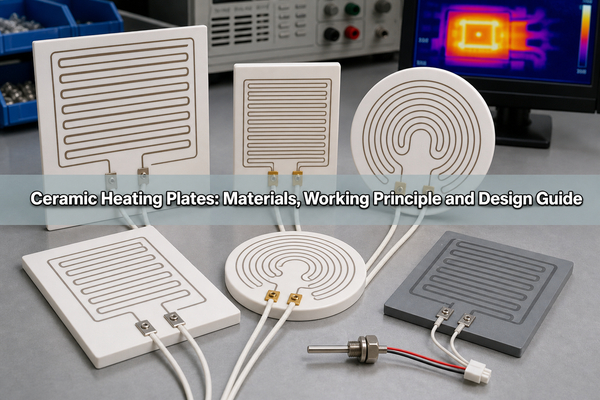
The correct design depends on more than maximum temperature. Substrate material, circuit construction, resistance, voltage, watt density, heated area, mounting contact, sensor position, and thermal cycling all affect warm-up time, uniformity, and service life. This guide explains how the main ceramic heater plate technologies differ and where each one fits.
What Are Ceramic Heating Plates?
A ceramic heating plate is an electrically insulating ceramic substrate combined with a resistive heating element. When voltage is applied, current through the resistive path converts electrical energy into heat. The ceramic then transfers that heat to a tool, fluid channel, wafer, sensor chamber, sealing surface, or other load.
Not every ceramic plate associated with heat is an active heater. A plain laser-cut alumina or AlN sheet placed behind a PCB is a passive heat spreader. It moves heat generated elsewhere but has no powered resistance circuit. An active ceramic plate heater includes conductors, resistor material, terminals, and usually a protective dielectric layer or co-fired ceramic cover.
Industrial designs are commonly produced as flat rectangles, discs, rings, narrow strips, or custom profiles. Holes, slots, sensor pockets, lead exits, mounting zones, and multiple heating zones can be incorporated when the ceramic process and mechanical limits allow.
How Do Ceramic Heating Plates Work?
The heating principle is resistive, also called Joule heating. Electrical power is converted into heat according to the relationship P = V x I. For a fixed resistance, the same relationship can be written as P = V²/R. A lower resistance at the same voltage therefore produces more power, while a higher resistance produces less.
The resistor pattern is not merely a wire drawn across a plate. Track width, thickness, sheet resistance, path length, turn spacing, terminal geometry, and local cooling conditions determine the electrical resistance and the surface heat flux. A well-designed pattern places more wattage where the assembly loses more heat and less where heat is trapped.
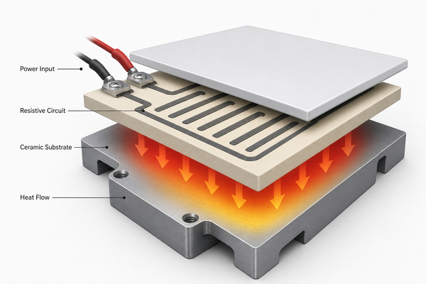
Heat moves from the resistance layer into the ceramic, then through the mounting interface and the heated load. The ceramic's thermal conductivity controls how quickly local heat spreads, while its thickness and heat capacity influence temperature gradients and response time. Air gaps, uneven clamping, thick adhesive, or a poorly placed sensor can dominate the result even when the ceramic itself has good thermal properties.
How Do MCH, Thick-Film and PTC Ceramic Heaters Differ?
Three technologies are often grouped under the broad term ceramic heater, but their construction and control behavior are different.
| Technology | Typical construction | Main strength | Important limitation |
|---|---|---|---|
| MCH ceramic heater | Metal resistance pattern embedded in ceramic green layers and co-fired into a monolithic body | Compact structure, fast response, protected internal circuit | Pattern and resistance changes are difficult after tooling and firing are established |
| Thick-film ceramic heater | Resistive and conductor pastes printed on a fired alumina or AlN substrate, then fired and protected | Flexible pattern design, distributed wattage, planar custom shapes | Surface layers and terminals require suitable protection from abrasion, moisture, and chemical exposure |
| PTC ceramic heater | Positive-temperature-coefficient ceramic element, commonly barium-titanate based, connected between electrodes | Resistance rises sharply with temperature, providing self-limiting behavior | Temperature and power are strongly affected by airflow, voltage, geometry, and material formulation |
MCH and thick-film heaters are appropriate when the equipment requires a defined resistance, controlled watt distribution, custom geometry, or close thermal contact. PTC elements are useful when self-regulation is valuable, but they are not a direct substitute for a precision plate heater with a specified temperature map.
Which Ceramic Materials Are Used for Heating Plates?
The ceramic must remain electrically insulating while carrying heat, supporting the resistor system, and surviving repeated temperature changes. Alumina and aluminum nitride are the most relevant materials for compact electronic heater plates. Silicon nitride and quartz are used in more specialized conditions.
| Material | Typical design position | Best suited to | Main trade-off |
|---|---|---|---|
| Alumina, Al2O3 | Mature, economical technical ceramic with useful thermal conductivity and strong insulation | Laboratory heaters, medical devices, sensors, sealing tools, compact industrial heating | Lower heat spreading than AlN |
| Aluminum nitride, AlN | High-thermal-conductivity electrical insulator | Wafer heating, concentrated heat loads, fast and uniform precision heating | Higher material and processing cost; moisture handling requires care |
| Silicon nitride, Si3N4 | Tough ceramic with strong thermal-shock and mechanical performance | Mechanically demanding or rapidly cycled environments | Heater process availability and property ranges are supplier-specific |
| Quartz | High-purity material with low thermal conductivity and high temperature capability | Optical, chemical, vacuum, and specialized radiant-heating systems | Poorer lateral heat spreading than dense AlN or alumina |
Published values should always be tied to a specific grade and temperature. For example, dense commercial alumina commonly transfers heat far better than organic PCB laminates, but its conductivity decreases as temperature rises. The existing Al2O3 thermal conductivity guide explains why purity, density, thickness, and test temperature change the result.
How Do Alumina and Aluminum Nitride Heating Plates Compare?
Alumina is usually the practical starting point when the heater area is not extremely concentrated and the required temperature uniformity can be achieved through pattern design, substrate thickness, and mounting. It supports mature thick-film processing, offers strong dielectric performance, and is available in several purity grades.
AlN is preferred when lateral heat spreading through the plate is a major constraint. Its much higher thermal conductivity can reduce hot spots and shorten the time needed for the surface to equalize. This is valuable in semiconductor tooling, analytical instruments, laser systems, and compact medical equipment where a small area must remain closely controlled.
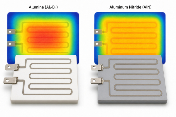
Higher conductivity does not automatically guarantee better performance. A thick bond layer, poor clamping, a small contact patch, asymmetric heat loss, or an incorrectly placed sensor can create a larger thermal error than the substrate. The material choice should follow an assembly-level thermal model rather than a conductivity number alone. For additional background, see aluminum nitride ceramic properties and applications.
How Are Ceramic Heating Plates Manufactured?
A surface thick-film heater begins with a fired ceramic substrate. The manufacturer cleans the surface, screen-prints conductor and resistor pastes, dries and fires each required layer, trims resistance when the process allows, adds a protective overglaze or dielectric, and joins terminals or lead wires. Multi-zone designs may use separate resistor networks and sensing traces on the same plate.
An MCH heater starts with ceramic green sheets. The resistance pattern is printed on an internal layer, the sheets are aligned and laminated, and the assembly is co-fired so the ceramic and metal system become one body. Terminations are then exposed, plated, brazed, or otherwise prepared for electrical connection.
Manufacturing control must account for paste sheet resistance, printed thickness, firing shrinkage, ceramic flatness, terminal adhesion, dielectric coverage, and resistance tolerance. A layout that is electrically correct can still fail if sharp corners concentrate current, conductor transitions overheat, or the lead joint sits inside the hottest zone.
BSTCeramicPCB supports thick-film ceramic PCB manufacturing on ceramic substrates, including printed conductors and resistive features where the released material system and design rules are compatible with the required heater construction.
How Should Resistance, Voltage and Power Density Be Designed?
The electrical design begins with the available voltage and required total power. For a resistive heater, the target resistance can be estimated from R = V²/P. A 24 V heater designed for 48 W, for example, needs a nominal hot-circuit resistance near 12 ohms. The cold resistance may differ because resistor materials have a temperature coefficient of resistance.
Total power is only the first check. Dividing power by the active heated area gives average watt density, but local watt density can be much higher near narrow tracks, terminals, corners, slots, or unheated mounting features. The resistance pattern should therefore be divided into thermal zones and checked against local heat loss.
- Use wider or lower-resistance sections where less heat is required.
- Use narrower or higher-resistance sections only where the ceramic and paste system can tolerate the local current density.
- Keep conductor-to-resistor transitions out of severe thermal gradients.
- Leave electrical clearance around holes, edges, metal clamps, and sensor pockets.
- Include the cold-to-hot resistance change when selecting the power supply and controller.
Power should be validated under the actual mounting and load condition. Open-air testing can produce a much higher element temperature than a test with the plate clamped to a thermal mass, even at the same voltage.
How Is Temperature Uniformity Controlled?
Temperature uniformity is created by coordinating the resistance pattern with the complete heat-loss map. Edges, mounting holes, lead exits, airflow, clamps, and contact with the load all pull heat away at different rates. A uniform-pitch serpentine trace often produces a nonuniform surface because the surroundings are not uniform.
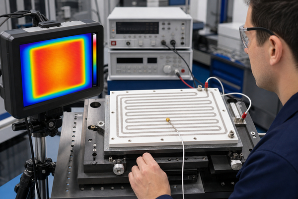
Distributed wattage addresses this problem by changing track geometry or using separately controlled zones. Edge zones may need more power to compensate for perimeter losses, while an insulated center may need less. A thermal simulation can guide the first pattern, but infrared mapping and contact-temperature measurements are still needed because interface resistance and assembly tolerances are difficult to model perfectly.
Flatness and mounting pressure matter as much as the printed pattern. A small air gap has poor thermal conductivity and can create a hot area in the heater directly above a cold area in the load. Mechanical retention should distribute pressure without bending the ceramic or restraining thermal expansion so strongly that cracking occurs.
How Should Temperature Be Sensed and Controlled?
A controller can only regulate the temperature measured by its sensor. If a thermocouple or RTD is placed near the resistor but far from the working surface, the controller may stop heating before the load reaches its target. If the sensor is far from both the heater and the load, thermal lag can cause overshoot.
Sensor location should represent the controlled surface and the dominant thermal delay. Small precision heaters may integrate an RTD or printed sensing resistor close to the active zone. Larger assemblies may use one control sensor and additional monitoring sensors at the center, edge, or load interface.
A closed-loop PID controller is common when stable temperature is required. The tuning must match the heater, ceramic mass, attached load, insulation, and airflow. Independent hardware protection, such as an over-temperature switch, current limit, fuse, or redundant sensor, is appropriate when a control failure could damage the ceramic, wiring, equipment, or process.
Where Are Ceramic Heating Plates Used?
Industrial ceramic heaters are selected where compact size, electrical insulation, clean construction, fast response, or elevated temperature operation is required. Typical uses include:
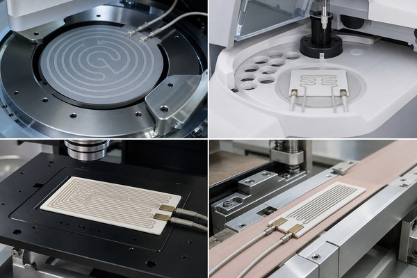
- Semiconductor wafer heating, bonding, probing, and process chambers.
- Medical analyzers, diagnostic cartridges, sterilization tools, and fluid warming.
- Laboratory instruments, sample stages, gas cells, and reaction chambers.
- Packaging and sealing equipment that needs a defined heated profile.
- Printer, dispensing, and microfluidic systems with localized heating.
- Automotive sensors, exhaust-related components, and compact thermal actuators.
- Vacuum equipment and analytical systems requiring low contamination and electrical isolation.
The same ceramic manufacturing platform can also carry conductors, resistors, sensors, and circuit features. This makes a heater plate useful when the design needs both thermal function and an integrated ceramic PCB structure.
What Are the Disadvantages of Ceramic Heating Plates?
Ceramic plates are rigid and brittle compared with metal or polymer heaters. Point loading, excessive clamping force, impact, sharp internal corners, and mismatched thermal expansion can cause cracking. Large, thin plates also require tighter flatness and handling control.
The manufacturing process is less forgiving than a replaceable wire heater. Fired resistance, geometry, metallization, protective layers, and terminations must work as one system. Design changes after qualification may require new screens, resistance tuning, firing trials, and thermal validation.
AlN and specialized ceramic heater constructions can cost more than alumina, mica, silicone rubber, or metal-sheathed alternatives. Ceramic is unnecessary when the temperature is moderate, flexibility is required, the heated surface is large and lightly loaded, or a standard heater can meet the thermal and insulation requirements.
What Causes Ceramic Heating Plate Failure?
Most failures are linked to local conditions rather than the ceramic's nominal maximum temperature. A plate can fail below that value if one section operates much hotter than the measured control point.
| Failure mode | Typical cause | Design response |
|---|---|---|
| Ceramic cracking | Mechanical point load, thermal shock, restrained expansion, poor flatness, or impact | Distribute clamping pressure, add compliant interfaces, control ramp rate, and avoid sharp geometry |
| Local resistor burnout | Excess watt density, narrowed print, paste defect, or an air gap under the hot zone | Review current density, print control, thermal contact, and zone power |
| Resistance drift | Repeated high-temperature exposure, oxidation, material interaction, or firing variation | Use a qualified paste system and validate hot resistance through cycling |
| Terminal or lead failure | Joint overheating, vibration, bending, or thermal-expansion fatigue | Move the joint away from the hottest area and provide strain relief |
| Leakage or dielectric breakdown | Cracked overglaze, contamination, moisture, insufficient clearance, or overvoltage | Control dielectric coverage, cleanliness, creepage, and hi-pot requirements |
| Temperature overshoot | Sensor lag, aggressive controller tuning, or loss of thermal load | Place sensors correctly and use independent over-temperature protection |
Qualification should reproduce the real mounting method, voltage, load, atmosphere, ramp rate, dwell time, and cooling cycle. A heater that passes a short open-air check may behave differently after thousands of cycles inside an assembly.
FAQ About Ceramic Heating Plates
How hot can you heat a ceramic plate?
The usable temperature is limited by the complete heater, not the ceramic alone. Alumina and AlN bodies can tolerate high temperatures, but the resistor paste, conductor, overglaze, brazed joint, lead wire, sensor, adhesive, and mounting interface may have lower limits. Use the qualified continuous and peak temperature for the released construction.
Do ceramic heaters use a lot of electricity?
Electricity use is determined by rated power and operating time. A 100 W plate at full power uses 0.1 kWh per hour. Closed-loop control reduces average consumption after reaching temperature, but the duty cycle depends on insulation, airflow, load, setpoint, and ambient conditions.
Are ceramic heating plates self-regulating?
Only PTC ceramic heaters have strong inherent self-limiting behavior. MCH and thick-film resistance heaters normally require a temperature sensor and controller. They should not be assumed to limit temperature automatically.
Can a ceramic heat spreader be converted into a heater?
A plain ceramic plate does not become a reliable heater by simply attaching power leads. It needs a designed resistance circuit, compatible conductor system, electrical clearances, protective layers, terminals, and thermal validation. A printed heater may be developed on a suitable ceramic substrate, but the structure must be designed as a heater from the beginning.
Is alumina or AlN better for a ceramic plate heater?
Alumina is often better when cost, mature processing, and good electrical insulation are the priorities. AlN is better when high lateral heat spreading, rapid equalization, or a concentrated heat load justifies the higher material and process cost. The mounting interface and resistor pattern must be optimized in either case.
Conclusion
Ceramic heating plates combine an electrically insulating substrate with a controlled resistive circuit. Alumina offers a mature and economical platform, while AlN supports faster spreading and tighter uniformity under concentrated heat loads. Reliable performance depends on the complete design: resistance, voltage, local watt density, ceramic thickness, pattern zoning, sensor location, mounting contact, and protection against thermal and mechanical stress.
BSTCeramicPCB supports ceramic substrates and thick-film circuit manufacturing for compact thermal and electronic structures. For a technical discussion about a ceramic heater or integrated ceramic circuit, contact sales@bstceramicpcb.com.
 Products
 About us
 Contact us



