



















































 HOME


-

Does Your Thin Film RTD Need a Custom Ceramic Circuit?
2026 11,04 -
4-Layer Alumina PCB: Stackup, Design Rules & Manufacturing Guide
2026 10,29 -
Aluminum Nitride Thermal Conductivity vs Temperature
2026 10,21 -
Wire Bonding EPIG Thickness: Selecting Pd/Au for Ceramic Bond Pads
2026 10,19 -
When Does a Thin-Film Circuit Need a Polished Alumina Substrate?
2026 10,18 -
Ceramic PCB for Humanoid Robot joint actuators
2026 04,07 -
LTCC PCB Surprises: What Most People Miss
2025 12,09 -
Step-by-Step Guide to DPC PCB Design for Sensor Systems
2025 12,03 -
Ceramic PCBs Essential Benefits and Applications
2025 12,01 -
How Al2O3 DPC Ceramic Substrate PCB Enhances Heat Dissipation in Modern Electronics?
2025 11,28 -
How to Choose Between Ceramic, FR4, and Metal Core PCBs
2025 11,27 -
DPC Ceramic PCB Materials: Surprising Science Inside
2025 11,26 -
Wire bondable 2-layer Alumina substrates PCB | Bstceramic PCB
2025 09,22 -
Silicon Nitride Substrate, Silicon Nitride Ceramic Substrate Formula
2025 05,08 -
What is thick film ceramic PCB?
2023 08,02
Does Your Thin Film RTD Need a Custom Ceramic Circuit?
Published:
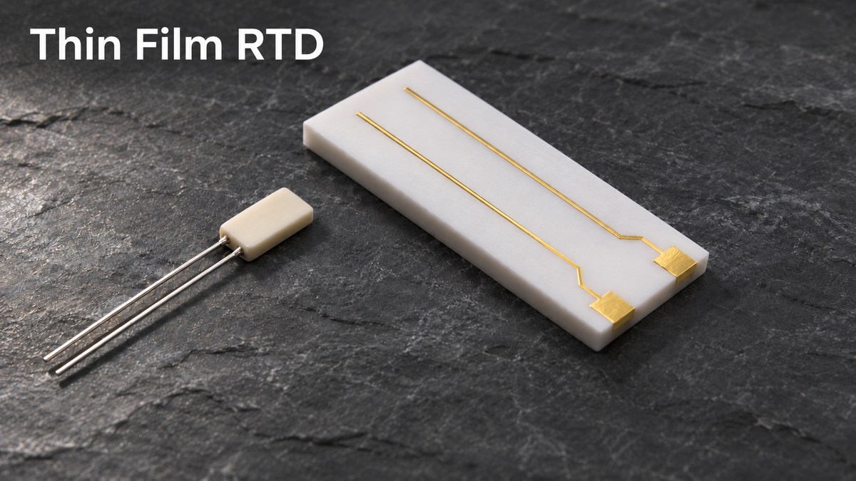
A standard thin film resistance temperature detector (RTD) can measure temperature with its own element and leads. Consider a custom ceramic circuit when the instrument needs the sensing element at a precise location, the connections at a different location, and a carrier to hold that geometry.
At BSTCeramicPCB, we can review the mounting drawing and pad layout before you order prototype circuits. Start by marking the surface or volume whose temperature you want to measure. That mark establishes where the element belongs and gives you a reference point for testing the assembled instrument.
When Does a Thin Film RTD Element Need a Separate Ceramic Circuit?
A separate ceramic circuit makes sense when it solves a mounting or routing problem that a standard element and its leads cannot accommodate. The element itself already contains a temperature-sensitive platinum film on an insulating substrate, often ceramic, with a protective layer over the film.
- One accessible measuring point. On a laboratory sample block, start with an element attached at the specified spot and leads routed to a nearby connector. Check how closely the reading follows the block during warm-up and after the temperature settles.
- Several fixed measuring points. If two elements must sit at defined coordinates and connect at one accessible edge, a patterned ceramic carrier can locate both elements and route their connections. Dimension each sensing position from the same mechanical datum. If fine conductors will be deposited on the carrier, specify a polished alumina substrate only when the film or feature size requires that finish.
- A carrier in the thermal path. If ceramic or adhesive will sit between the element and the block, mark the contact area on the drawing. Test that mounting arrangement before setting the instrument’s response-time requirement.
Thin Film vs Wire Wound RTD: Which Fits Your Instrument?
Start with thin film for a shallow measuring point or a vibration-prone assembly. Compare wire-wound models when the instrument needs tight tolerance across a broad temperature range. The decision depends on the rating of the specific part and how it will be mounted.
| Selection criterion | Thin film RTD | Wire-wound RTD |
|---|---|---|
| Sensing structure | Patterned film on substrate | Fine wire on insulating support |
| Mounting clearance | Planar body and lead exit | Winding diameter and housing depth |
| Vibration review | Element attachment and lead support | Winding support and assembly rating |
| Wide-range accuracy | Class limits at temperature extremes | Specified tolerance and long-term drift |
If response speed decides the purchase, compare data at the same response threshold, medium, flow speed, and housing configuration. A bare element tested in moving air and a sheathed probe tested in water cannot be ranked by their published times alone.
Pt100 or Pt1000: Which Thin Film RTD Element Should You Choose?
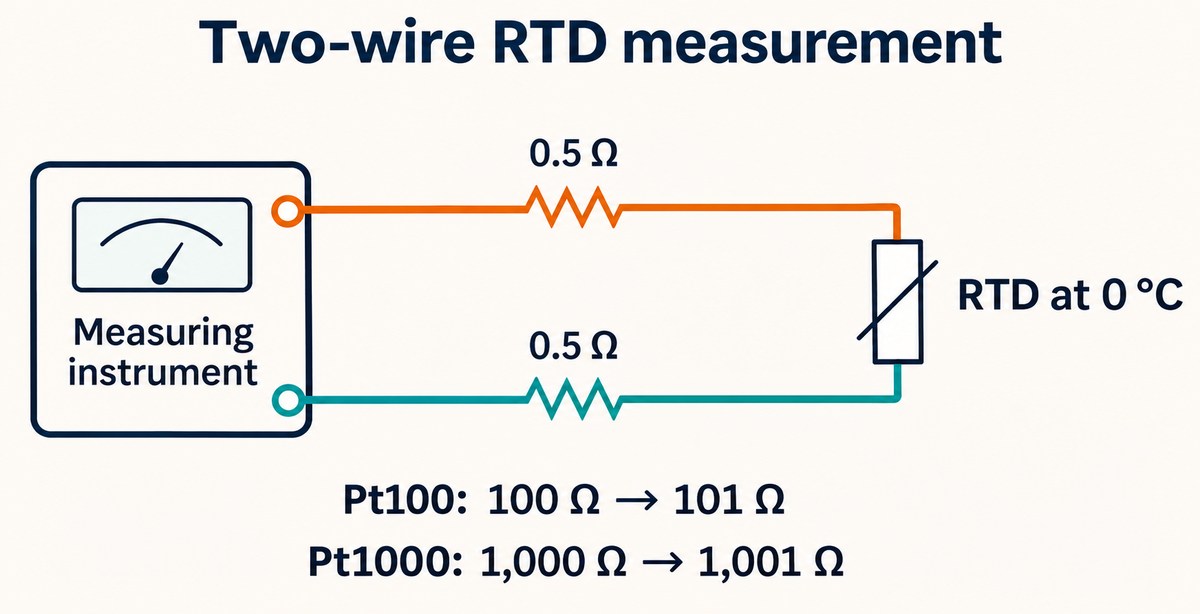
Choose the resistance curve and wiring configuration supported by your instrument input. A Pt100 measures nominally 100 Ω at 0 °C and a Pt1000 measures 1,000 Ω. If the input supports both, compare lead error and self-heating at the intended excitation current.
- Two-wire lead error. At 0 °C, a total lead resistance of 1 Ω adds 1% to a Pt100 reading and 0.1% to a Pt1000 reading. These percentages describe resistance error. Temperature error depends on the selected RTD curve.
- Excitation current. Power follows P = I²R. At the same current, the higher-resistance element dissipates more power. Check the current specified for your selected part before configuring the input.
The following values come from the Heraeus M222 datasheet, document 30910015, Index B, June 2016. Confirm the current specification for the exact order number before purchasing.
| M222 specification | Datasheet value | Applicable condition |
|---|---|---|
| Temperature coefficient | 3,850 ppm/K | M222 platinum elements |
| Continuous operating range | −70 to +500 °C | Continuous exposure |
| Class A tolerance range | −50 to +300 °C | Class A versions only |
| Pt100 measuring current | 0.3–1.0 mA | 100 Ω at 0 °C |
| Pt1000 measuring current | 0.1–0.3 mA | 1,000 Ω at 0 °C |
| Self-heating coefficient | 0.4 K/mW | At 0 °C |
Worked example. At 0 °C and 1 mA, a Pt100 dissipates 0.1 mW. Multiplying by the listed 0.4 K/mW gives an estimated temperature rise of 0.04 °C under the reference conditions. Check self-heating again after assembly because the mount changes how readily heat leaves the element.
What Determines Thin Film RTD Response Time in Air?
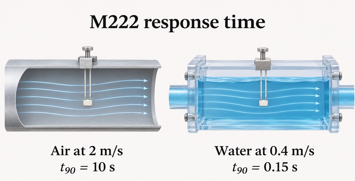
Air speed, element position, and the thermal path through the mount all affect how quickly the reading follows a temperature change. The M222 data show why the test conditions belong next to every response-time value. Here, t90 is the time to reach 90% of a temperature step.
| M222 test medium | Flow speed | Response time (t90) |
|---|---|---|
| Moving air | 2 m/s | 10 s |
| Flowing water | 0.4 m/s | 0.15 s |
Heraeus specifies dry environments for unhoused use. The water-flow test provides a comparison under a defined laboratory condition.
- Reproduce the installation. For an air measurement, record airflow and sensor position. For a surface measurement, record the attachment method, contact area, and reference sensor location.
- Measure lag. Apply a repeatable temperature step and record the assembled sensor’s t90. Use this result when setting the instrument’s response requirement.
- Measure offset. Hold the temperature steady and compare the final RTD and reference readings. This separates a persistent measurement error from a slow response.
What Should a Ceramic Circuit RFQ Include for a Thin Film RTD?
Specify what you want quoted: a bare ceramic circuit, a carrier for a separately sourced element, or an assembled part. Include the RTD order number and datasheet if selected, then provide the drawing and acceptance criteria below.
| RFQ input | Details to specify |
|---|---|
| Carrier drawing | Material, outline, thickness, datum, sensing coordinates |
| Mounting interface | Contact area, attachment method, available clearance |
| Electrical layout | Pad locations, lead routing, connector position |
| Service conditions | Temperature range, medium, airflow, vibration |
| Prototype acceptance | Reference location, excitation current, allowable offset, target t90 |
| Supply responsibilities | Element supplier, assembly responsibility, sample and production quantities |
Why Choose BSTCeramicPCB for Ceramic Circuit Design Review?
BSTCeramicPCB can review whether the proposed carrier is practical to build and support a small prototype run. For an RTD project, the most useful review happens while the sensing position, mounting interface, and pad layout can still change.
- DFM pre-review. Our engineers can flag missing datums, ambiguous sensing coordinates, or pads that will be difficult to reach after mounting. You can resolve those points on the drawing before ordering samples.
- Dedicated 1+3 Technical Support Team. One dedicated sales representative works with three engineers to support your project from design review and prototyping to production. Whether you need to confirm RTD sensing positions, ceramic material selection, pad layout, or mounting requirements, our team provides coordinated technical feedback and practical manufacturing solutions tailored to your design.
- Prototype and small-batch support. Use the first carriers to check fit and connection access. Your instrument team can then measure response time and steady-state error in the intended mount before releasing the production layout.
- ISO 13485 certification for supplier qualification. If your RTD carrier is part of a medical instrument, your quality team can use BSTCeramicPCB’s ISO 13485 certificate to review the scope of our quality management system during supplier approval.
FAQs About Thin Film RTDs
Is every Pt100 a thin film RTD?
No. Pt100 identifies the nominal platinum resistance at 0 °C. Check the part’s construction to distinguish thin film from wire-wound versions.
Is the ceramic substrate the sensing element?
The platinum film senses temperature through its change in resistance. The ceramic provides mechanical support and electrical insulation.
Does Class A apply throughout the operating range?
Only within the interval specified for that grade. For the cited M222, +400 °C falls within continuous operation but above the published Class A limit of +300 °C.
Can I use the water response time for a surface-mounted sensor?
Measure t90 on the intended surface. Bond thickness, contact area, and the carrier all influence how quickly heat reaches the film.
How can I check whether the measuring current is warming the RTD?
At a stable reference temperature, compare settled readings at two currents within the element’s specified range. A repeatable rise at the higher current warrants a closer check of self-heating.
What changes when a bare element goes into a probe?
The sheath, fill material, and element position change heat transfer. Request response data for the complete probe under conditions close to your application.
When a thin film RTD needs a custom ceramic carrier, BSTCeramicPCB can review the sensing position, pad layout, and mounting interface for manufacturability, then support a small prototype run so your team can test the fit and thermal response. Send your mounting drawing, RTD datasheet, operating range, and sample quantity to sales@bstceramicpcb.com.
 Products
 About us
 Contact us